


132
XtrapulsPac – User Guide
Chapter 3 - Reference
Homing Operation Indicator
Index 0x3218
Name
Homing Operation Indicator
Object Code
VAR
Data Type
Unsigned16
Object Class
all
Access rw
PDO Mapping
No
Default Value
0
This object allows keeping the result of a homing operation:
- it is cleared when drive is switched on
- it is set if the position sensor is absolute multi-turn.
- it is set after a successful homing.
- it is cleared if the position sensor is lost (by any fault related to this sensor).
- if a special homing function is implemented in the master, the master needs to set this object after that special
homing is complete.
3.2.3.5 - Interpolated Position Mode
Interpolated Position Mode
The interpolated position mode is used to control several axes in coordination. The trajectory must be generated
by the host controller and the elementary set point is sent at a fixed cycle time (same as communication cycle
time) to all axes.
The cycle time synchronization of all axes is ensured by the SYNC message. The setpoint data flow must be sent
in real-time.
The elementary set point could be only position if linear interpolation is chosen. The PV interpolation mode
requires position and velocity for each set point. The P3 cubic interpolation mode requires only position set point
because the interpolator is using the three last position set points. However, the interpolation error is inherent
when the acceleration is changing with the P3 cubic interpolation mode.
Both cubic interpolation modes require high position resolution when operating at low speed values. At very low
speed, the linear interpolation mode is giving best results.
The CAN bus Interpolator is running in any mode but the result of the interpolator (0x30C1) is applied to the
position loop only in Interpolated Position Mode.
When using the linear interpolation, the feedforward acceleration term (KAv) must be cleared (see interpolation
and servo loop). Only a PV or P3 interpolation can fully support a feedforward acceleration term.
Index Object
Name
Type
Attr.
0x60C0
VAR
Interpolation Submode Select
Integer16
rw
0x60C1
RECORD
Interpolation Data Record
rw
0x60C4
RECORD
Interpolation Data Configuration
rw
0x30C1
VAR
Interpolated Data Output
Integer32
rw
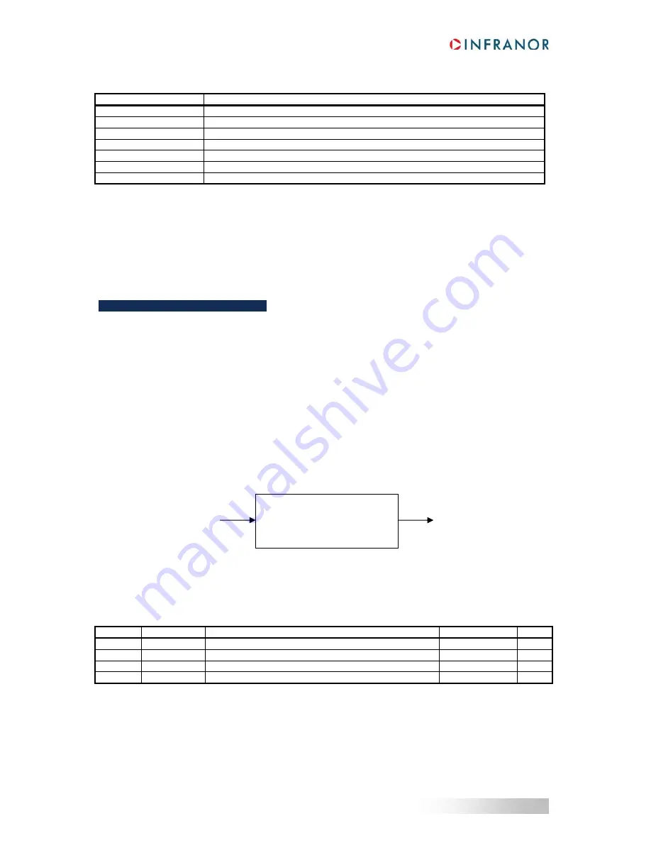
Data Flow from
CAN bus
0x60C1
CAN bus Interpolator
0x60C0
Interpolated Data
Output
0x30C1


