


12
XtrapulsPac – User Guide
Chapter 2 - Commissioning
2.4.2.2 - Manual motor configuration
If the motor configuration must be manually made (motor is not referenced in the
Gem Drive Studio
catalog),
adjust first the motor position sensor parameters (resolver or encoder) before the motor parameters.
Configuration of the motor thermal sensor
Selection of the sensor type
The motor can be equipped either with a CTN sensor (ohmic resistance = decreasing temperature function) or
with a CTP sensor (ohmic resistance = increasing temperature function).
Check that the selected thermal sensor type actually corresponds to the sensor type mounted on the application
motor.
Triggering threshold adjustment
Enter the sensor ohmic value (kOhm) corresponding to the required temperature value for the release of the
motor over-temperature protection, according to the manufacturer's specifications.
Warning threshold adjustment
Enter the sensor ohmic value (kOhm) corresponding to a warning temperature value.
When the warning temperature is reached, the warning bit in status word is set.
Note
When using a CTN sensor, the warning ohmic value will be higher than or equal to the triggering ohmic value.
When using a CTP sensor, the warning ohmic value will be lower than or equal to the triggering ohmic value.
Current limit adjustment
The
Maximum current
parameter defines the maximum output current value of the drive. It may vary between
20 % and 100 % of the drive current rating.
The
Rated current
parameter defines the limitation threshold of the drive output RMS current (I
2
t). It can vary
between 20 % and 50 % of the drive current rating.
I²t protection adjustment
2 selection modes are available: Fusing or Limiting.
It is advisable to use the Fusing mode during the commissioning phases.
In
Fusing
mode, the drive is disabled when the current limitation threshold is reached.
In
Limiting
mode, the motor current is only limited at the value defined by the
Rated current
parameter when the
limitation threshold is reached.
Operation of the Current Limitation in "Fusing" Mode
When the drive output RMS current (I
2
t) reaches 85 % of the rated current, the I²t warning is displayed. If the RMS
current (I
2
t) has not dropped below 85 % of the rated current within 1 second, the I
2
t error is released and the
drive disabled (otherwise, the I²t warning is removed).
When the drive output RMS current (I
2
t) reaches the rated current value, the I
2
t limits the drive output current at
this value.
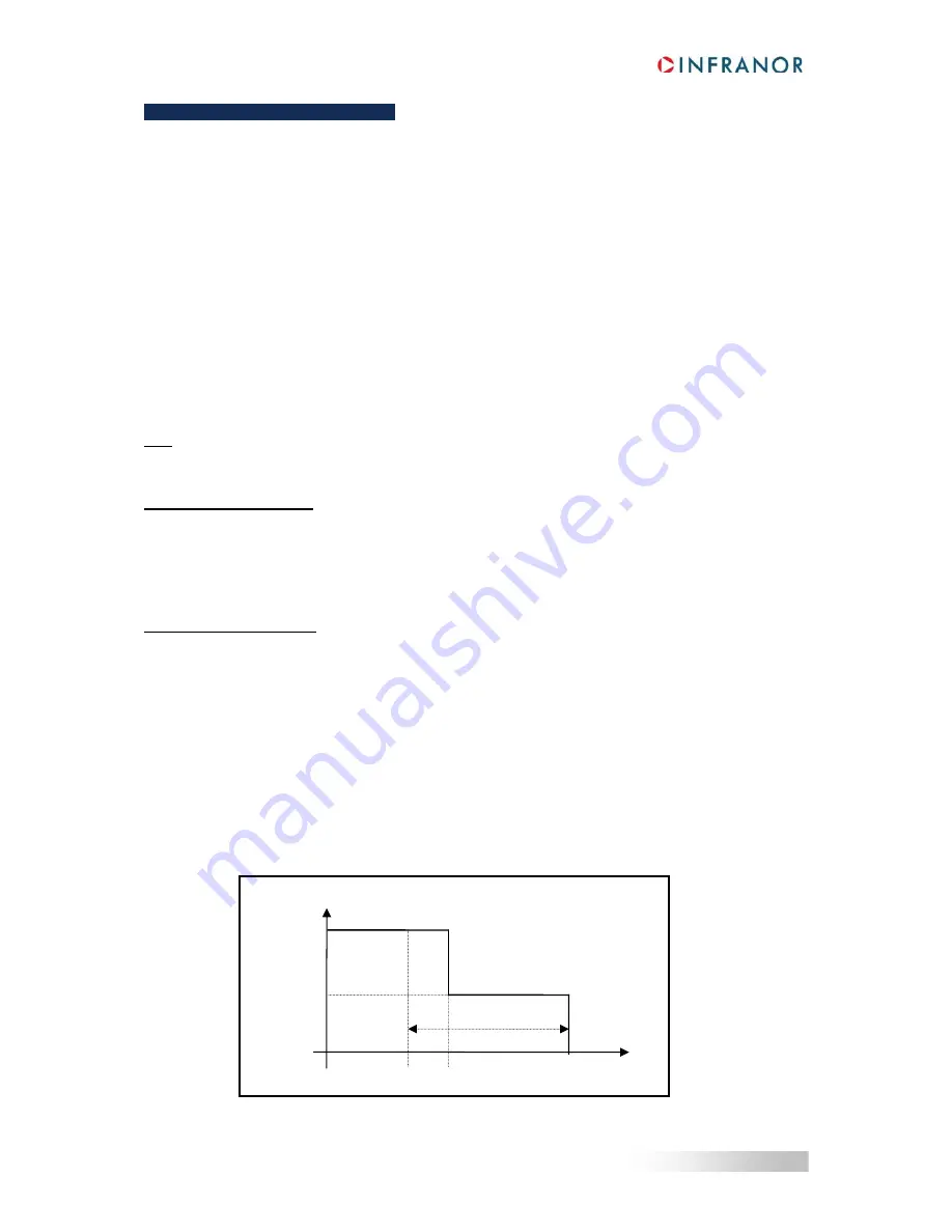
Diagram of the drive output current limitation in an extreme case (motor overloaded or shaft locked):
Max. current
t0
t3
Rated current
t1
t2
Drive output current
1 second


