background image


 Safety information

  1


DANGER

Electrical current from power, telephone, and
communication cables is hazardous.

To avoid a shock hazard:

– Do not connect or disconnect any cables or

perform installation, maintenance, or
reconfiguration of this product during an
electrical storm.

– Connect all power cords to a properly wired and

grounded electrical outlet.

– Connect to properly wired outlets any

equipment that will be attached to this product.

– When possible, use one hand only to connect or

disconnect signal cables.

– Never turn on any equipment when there is

evidence of fire, water, or structural damage.

– Disconnect the attached power cords,

telecommunications systems, networks, and
modems before you open the device covers,
unless instructed otherwise in the installation
and configuration procedures.

– Connect and disconnect cables as described in

the following table when installing, moving, or
opening covers on this product or attached
devices.


70

Netfinity 3500 M10 User's Handbook 


Summary of Contents for Netfinity 3500 M10

Page 1: ...Netfinity 3500 M10 User s Handbook...

Page 2: ......

Page 3: ...Netfinity 3500 M10 User s Handbook IBM...

Page 4: ...described in this publication at any time This publication was developed for products and services offered in the United States of America and the United Kingdom It is possible that this publication...

Page 5: ...t features 14 Changing keyboard speed 15 Using locks 16 Chapter 3 Using the Configuration Setup Utility Program 17 Starting and using the program 19 Overview 25 Instructions for common procedures 41 Q...

Page 6: ...hanging the battery 194 Chapter 7 Getting help service and information 197 Service support 199 Before you call for service 200 Getting customer support and service 201 Purchasing additional services 2...

Page 7: ...dette produkt Ennen kuin asennat t m n tuotteen lue turvaohjeet kohdasta Safety Information Avant d installer ce produit lisez les consignes de s curit Vor der Installation dieses Produkts die Sicher...

Page 8: ...sobre Seguran a Pred in tal ciou tohto zariadenia si pe taje Bezpe nostn predpisy Antes de instalar este producto lea la informaci n de seguridad L s s kerhetsinformationen innan du installerar den h...

Page 9: ...any equipment that will be attached to this product When possible use one hand only to connect or disconnect signal cables Never turn on any equipment when there is evidence of fire water or structura...

Page 10: ...Attach signal cables to connectors 4 Attach power cords to outlet 5 Turn device ON To Disconnect 1 Turn everything OFF 2 First remove power cords from outlet 3 Remove signal cables from connectors 4...

Page 11: ...em has a module containing a lithium battery replace it only with the same module type made by the same manufacturer The battery contains lithium and can explode if not properly used handled or dispos...

Page 12: ...ve is certified to conform to the requirements of the International Electrotechnical Commission IEC 825 and CENELEC EN 60 825 for Class 1 laser products 3 CAUTION When laser products such as CD ROMs D...

Page 13: ...laser diode Note the following Laser radiation when open Do not stare into the beam do not view directly with optical instruments and avoid direct exposure to the beam 4 CAUTION Use safe practices whe...

Page 14: ...xii Netfinity 3500 M10 User s Handbook...

Page 15: ...nfiguration conflicts Chapter 4 Taking care of your server provides guidelines for the proper handling and care of your server Chapter 5 Installing options contains instructions for installing and rem...

Page 16: ...ins instructions for setting switches Appendix B Product warranties and notices contains warranty information notices and trademarks An index follows the appendixes Notices used in this book This book...

Page 17: ...d installing an operating system The ServerGuide package which contains serveral CD ROMs describes the advantages of IBM ServerGuide and how to use the ServerGuide software The Safety Book is also inc...

Page 18: ...xvi Netfinity 3500 M10 User s Handbook...

Page 19: ...ormation about your Netfinity 3500 M10 server model and other IBM server products at the following World Wide Web address http www ibm com netfinity Your server serial number and model number are loca...

Page 20: ...nents This chapter contains Features at a glance 3 Getting started 4 Questions or problems 5 Arranging your workspace 6 Comfort 6 Glare and lighting 7 Air circulation 7 Electrical outlets and cable le...

Page 21: ...additional internal and external SCSI devices Support for 3 5 inch 1 44 MB diskette drive internal tape drive Support for Netfinity ServeRAID adapters Power supply 330 W 115 230 V ac 50 60 Hz Automati...

Page 22: ...hardware in your server If you have not already done so unpack and set up your server Refer to the Start Here booklet for instructions If you are not installing any optional hardware now connect the...

Page 23: ...n days a week during your first 90 days after installation1 Assistance is available for IBM and non IBM network operating systems network interface adapters and other optional peripherals For more inf...

Page 24: ...est and seat should adjust independently and provide good support The seat should have a curved front to relieve pressure on the thighs Adjust the seat so that your thighs are parallel to the floor an...

Page 25: ...y of the image on the screen try them only after you have exhausted other methods of reducing glare Dust buildup compounds problems associated with glare Remember to clean your monitor screen periodic...

Page 26: ...see Power cord notice on page 235 Cabling the server Before cabling your server Make sure you have an adequate number of properly grounded outlets for the server and any other devices Select a locati...

Page 27: ...pansion slot 4 PCI 8 Expansion slot 3 PCI 9 Expansion slot 2 PCI 1 Expansion slot 1 AGP 11 Microphone connector 12 Audio line in connector 13 Audio line out connector 14 Ethernet connector 15 Serial p...

Page 28: ...the power cords to the server and other devices first then plug the cords into properly grounded electrical outlets When the power cord is first plugged in the server powers on for a few seconds then...

Page 29: ...normally operate with a single touch However in some circumstances the server may not immediately power off In this case hold the power switch down for approximately 5 seconds The server will then tu...

Page 30: ...AN Activity Light Power Switch Power On Light The following describes the operating controls and status indicators located on the front of your server Power Switch Press this switch to turn your serve...

Page 31: ...er On Light This status indicator lights when you turn on your server Hard Disk Drive Light When this light is on it indicates that the hard disk drive is in use LAN Activity Light When this light bli...

Page 32: ...sers are provided by all major operating systems and all major LAN management packages including Netfinity Manager Intel LANDesk and Microsoft SMS Your server has hardware integrated on the system boa...

Page 33: ...work LANClient Control Manager recognizes your computer as a Hybrid RPL client and a bootstrap program is downloaded to your computer This bootstrap program is small and helps prevent network congesti...

Page 34: ...space provided in Appendix A Server records and specifications on page 211 Store the tag in a safe place Locking the keyboard You can disable the keyboard so that others are unable to use it If a powe...

Page 35: ...Setting the startup sequence 53 Setting remote administration 54 Understanding power management 55 Quick reference for network related settings 58 The Configuration Setup Utility program is stored in...

Page 36: ...Utility Overview on page 25 which contains descriptions of the configuration and setup options by categories Instructions for common procedures on page 41 which contains more detailed instructions and...

Page 37: ...the screen during startup press F1 The Configuration Setup Utility program prompt appears on the screen for only a few seconds You must press F1 quickly 3 If you have not set an administrator password...

Page 38: ...e the same way Configuration Setup Utility Select Option System Summary Product Data Devices and I O Ports Start Options Date and Time System Security Advanced Setup ISA Legacy Resources Power Managem...

Page 39: ...m with a 5 beside it If an asterisk appears next to a menu item it indicates a system resource conflict Resolve this conflict before exiting from the Configuration Setup Utility program so that your s...

Page 40: ...r hyphen key in some menus to decrease the numerical value of a setting 0 9 Use these number keys in some menus to change the numerical value of a setting F1 Press this key for help on a selected menu...

Page 41: ...prompted to Continue or Exit Setup Select Continue If you select Exit Setup you will get another error message 2 The Configuration Setup Utility program menu appears with a right arrowhead 5 next to...

Page 42: ...rogram you might have to press Esc several times to get back to the Configuration Setup Utility program menu 2 Before you exit from the Configuration Setup Utility program menu select Save Settings if...

Page 43: ...memory is special buffer storage that holds frequently used instructions and data and works faster than main memory Cache State Indicates the state of cache memory enabled or disabled System Memory In...

Page 44: ...automatically if the EEPROM electrically erasable programmable read only memory or BIOS basic input output system code is upgraded Product Data Descriptions Machine Type Model Shows the type and model...

Page 45: ...on to set the correct type Serial Port Setup Serial Port A Address Serial Port A IRQ Serial Port B Address Serial Port B IRQ The Serial Port Setup menu shows the addresses and interrupts for the built...

Page 46: ...ECP and EPP or Bidirectional In standard mode you are limited to write only unidirectional mode The extended modes are bidirectional and will increase the efficiency of your parallel port however the...

Page 47: ...ectable performance The performance indicates the speed at which the drive will transfer data To get better disk performance run IDE hard disk and the CD ROM drives in High Performance mode If an IDE...

Page 48: ...u want to automatically start the Configuration Setup Utility whenever a POST error occurs Select another option if you want the system to bypass the Configuration Setup Utility and use a different st...

Page 49: ...er on sequence This setting does not affect the behavior of these keys only the display of the options Power On Status Use this option to control whether or not power on status indicators such as memo...

Page 50: ...administrator passwords System Security Descriptions Enhanced Security If your model has the Enhanced Security feature this option on the System Security menu shows the current setting for enhanced s...

Page 51: ...o On the prompt option will be reset to Dual when Remote Administration is set to Enabled Power On Password Use this option to set change or delete a power on password You can also set Password Prompt...

Page 52: ...an main memory With cache memory enabled most of your programs will run faster If you run programs that require slower speeds you can disable cache memory to slow down your server ROM Shadowing The RO...

Page 53: ...if the bus master function is enabled when the system is restarted Note If PCI adapters do not operate properly you might need to disable the PCI Bus Master option Plug and Play Control Set Device No...

Page 54: ...supports unpredictable results might occur The Processor ID is displayed Enabling or disabling Processor Updating determines whether the BIOS will apply microprocessor updates when the server starts E...

Page 55: ...setting for an available hexadecimal address Be sure to read the documentation that comes with your adapter You might need to make changes to the adapter to accommodate the selections you make for Me...

Page 56: ...es For example you might have to move jumpers or switches on the adapter or make changes to the software that comes with the adapter Interrupt Resources Use Interrupt Resources to allocate interrupt r...

Page 57: ...supports Display Power Management Signaling DPMS Power Management Options Descriptions APM APM BIOS Mode Automatic Hardware Power Management Time to Low Power IDE Drives Activity Monitor PS 2 Keyboar...

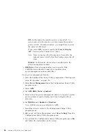
Page 58: ...automatically turn on your server You must also select the startup sequence you want to use for the type of power on event selected If you select Automatic make sure Automatic Power On Startup Sequenc...

Page 59: ...ding on your model and configuration your screen might appear slightly different from the one shown here System Summary Processor Pentium III Processor Speed 500 MHz2 Dual Processor Enabled L2 Cache S...

Page 60: ...ur operating system might also have a function for setting the date and time Refer to your operating system documentation for more information Understanding the power on password The power on password...

Page 61: ...ing Windows NT Server and have a mouse connected to the mouse port a serial mouse is not affected by the password prompt Off mode The password prompt Off mode prevents the server from detecting that a...

Page 62: ...omputer power switch or by an unattended method such as a modem or timer If you start the server by using the power switch the computer operates the same as it does in password prompt On mode Refer to...

Page 63: ...ep a record of your power on password in a secure place When a power on password has been set you cannot activate the keyboard and mouse without first using the password If you lose or forget your pas...

Page 64: ...ility program press Esc and follow the instructions on the screen Deleting a power on password Use the Configuration Setup Utility program to delete a power on password To delete a power on password 1...

Page 65: ...an administrator password When you set an administrator password a password prompt appears each time you try to access the Configuration Setup Utility program The password does not appear on the scree...

Page 66: ...ystem board Refer to Erasing a lost or forgotten administrator password on page 49 for further information 2 If enhanced security is enabled you must replace the system board in your server To set or...

Page 67: ...the Configuration Setup Utility program menu 3 Select Administrator Password 4 Select Delete Administrator Password and follow the instructions on the screen 5 Press Esc until you return to the Config...

Page 68: ...ry that stores your configuration setup and security settings The information stored in CMOS remains there for the life of the battery as long as the battery is not removed Your server has an enhanced...

Page 69: ...ystem programs EEPROM is write protected with a soft lock A soft lock allows the POST BIOS update utility to function in a network environment Enhanced security adds a hard lock With a hard lock when...

Page 70: ...your administrator password if you have set an administrator password The server remains in a halted state until you enter the administrator password 4 When you enter the administrator password the u...

Page 71: ...nhanced security is enabled it is vital that you keep a record of your administrator password in a secure place If you forget or lose the administrator password the system board in your server must be...

Page 72: ...able remote administration you can have your server system programs such as POST BIOS updated remotely from a network server If you have set an administrator password for your server it does not have...

Page 73: ...management features With Power Management the server and monitor if a monitor is attached and the monitor supports DPMS can be set to go into a reduced power state if they are inactive for a specified...

Page 74: ...tions take affect To set power management features 1 Start the Configuration Setup Utility program see Starting and using the program on page 19 2 Select Power Management from the Configuration Setup...

Page 75: ...ake on LAN When you set Wake on LAN to Enabled your server will turn on when it receives a specific signal from another computer on your local area network LAN Wake Up on Alarm With this feature you c...

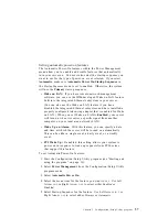
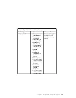
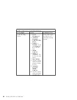
Page 76: ...fferent setting When finished you can either save the settings and exit the utility or exit without saving the settings The steps in the following tables always start at the Configuration Setup Utilit...

Page 77: ...ou select Enabled continue to the next step 5 Startup Sequence 6 Primary or Automatic Go back to the main menu 7 Start Options 8 The first second third and fourth primary startup devices 9 Automatic P...

Page 78: ...isabled If you select Enabled go to the next step 5 Startup Sequence 6 Primary or Automatic Go back to the main menu 7 Start Options 8 The first second third and fourth primary startup devices 9 Autom...

Page 79: ...you select Enabled go to the next step 5 Startup Sequence 6 Primary or Automatic Go back to the main menu 7 Start Options 8 The first second third and fourth primary startup devices 9 Automatic Power...

Page 80: ...62 Netfinity 3500 M10 User s Handbook...

Page 81: ...are of your server This chapter provides guidelines for the proper handling and care of your server This chapter contains Cleaning the mouse 64 Replacing the battery 64 Moving your server 65 Copyright...

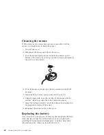
Page 82: ...Wash the ball in warm soapy water and dry it well 6 Using a damp cloth wipe the outside of the mouse and the retainer Be sure to wipe the rollers inside the mouse 7 Insert the ball and retainer Lock...

Page 83: ...battery replace it only with the same module type made by the same manufacturer The battery contains lithium and can explode if not properly used handled or disposed of Do not Throw or immerse into w...

Page 84: ...media diskettes compact discs tapes and so on from the drives 3 Turn the server and all attached devices off Your hard disk drive automatically parks the read write heads in a nondata area This proces...

Page 85: ...mponents 78 Working with options on the system board 82 Identifying parts on the system board 82 Accessing the system board 84 Working with system memory 86 Installing a DIMM 88 Removing a DIMM 91 Wor...

Page 86: ...Interrupt and DMA resources 144 Interrupt resources 144 DMA resources 146 68 Netfinity 3500 M10 User s Handbook...

Page 87: ...ou intend to install Place your server in a location that is dry Rain or spilled liquids might damage your server Have a supply of 2 MB 1 44 MB formatted 3 5 inch diskettes available Back up all impor...

Page 88: ...equipment that will be attached to this product When possible use one hand only to connect or disconnect signal cables Never turn on any equipment when there is evidence of fire water or structural d...

Page 89: ...are present inside any component that has this label attached There are no serviceable parts inside these components If you suspect a problem with one of these parts contact a service technician To C...

Page 90: ...pters and memory modules by the edges Never touch any exposed circuitry Prevent others from touching components When you are installing a new option touch the static protective package containing the...

Page 91: ...AGP adapters Internal drives Asset security Cover lock Security U bolt For the latest information about available options Look on the following World Wide Web pages http www ibm com pc options http ww...

Page 92: ...specific option and are noted in the instructions that come with the option 74 Netfinity 3500 M10 User s Handbook...

Page 93: ...nformation on page 70 and Handling static sensitive devices on page 72 Read Using the stabilizing feet Using the stabilizing feet The four feet attached to the bottom cover rotate 90 degrees to provid...

Page 94: ...connect the telephone line from the wall outlet and the server 4 Disconnect all cables attached to the server this includes power cords input output I O cables and any other cables connected to the se...

Page 95: ...7 Slide the cover toward the front of the server and lift it off Cover Release Tab Chapter 5 Installing options 77...

Page 96: ...adapters and devices preinstalled A graphics adapter A CD ROM drive in drive bay 1 A diskette drive in drive bay 4 For more information on drive bays see Internal drives on page 110 The following ill...

Page 97: ...n light 3 Hard disk drive in use light 4 LAN activity light 5 Bay 1 CD ROM drive 6 CD ROM eject button 7 CD ROM emergency eject hole behind the bezel on some models 8 CD ROM drive in use light 9 Bay 2...

Page 98: ...from the front For information on removing the cover see Preparing to install and remove options on page 75 1 Upper drive bracket bays 1 4 2 Lower drive bracket bays 5 6 3 System board 4 Video adapter...

Page 99: ...is a panel that provides access to I O connectors Adapters installed in expansion slots might also provide I O connectors Monitor USB 1 RJ45 Ethernet Audio Line Out Keyboard Serial 2 Serial 1 Parallel...

Page 100: ...on page 100 Identifying parts on the system board The system board also called the planar or motherboard is the main circuit board in your server It provides basic computer functions and supports a va...

Page 101: ...l B SCSI connector 50 pin 1 Secondary IDE connector 11 Battery 12 CMOS clear password jumper 13 Rocker switches 14 Wake on LAN connector 15 Wake on Modem connector 16 Channel A SCSI connector 68 pin 1...

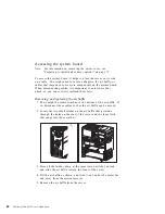
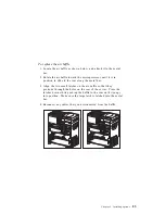
Page 102: ...later Removing and replacing the air baffle 1 There might be cables attached to the bottom of the air baffle If so disconnect these cables so that the air baffle can be moved 2 Locate the two small la...

Page 103: ...the rear along the metal bar 3 Align the two small latches on the air baffle so that they protrude through the holes on the rear of the server Press the latches down while pushing the baffle to the r...

Page 104: ...not mix registered and unregistered DIMMs The 64 MB and 128 MB DIMMs are unregistered memory technology The 256 MB DIMM is registered memory technology The Netfinity 3500 M10 does not support EDO mem...

Page 105: ...le and additional information can be found on a label located inside your server Again alternative configurations are possible Note Values in the following table are represented in megabytes MB DIMM c...

Page 106: ...options on page 75 Read Accessing the system board on page 84 Note For information on memory configuration see Memory configuration on page 87 1 See Identifying parts on the system board on page 82 t...

Page 107: ...c protective package containing the DIMM to any unpainted bare metal surface in the server and then remove the DIMM 5 Position the DIMM above the connector so that the two notches on the bottom edge o...

Page 108: ...above 9 Go to the device record form in Appendix A Server records and specifications on page 211 and record the appropriate information What to do next To work with another option go to the appropria...

Page 109: ...em board To locate the desired DIMM see Identifying parts on the system board on page 82 2 If an adapter the air baffle or cables restrict your access to the memory connectors you might have to remove...

Page 110: ...g and replacing the air baffle on page 84 6 Store the DIMM in a static protective package What to do next To work with another option go to the appropriate section To complete the installation go to C...

Page 111: ...ons and other applications The voltage regulator function is built into the system board This feature supports each microprocessor on the system board If you install a second microprocessor it must op...

Page 112: ...ver Disconnect all cables attached to the server and remove the server cover see Preparing to install and remove options on page 75 Read Accessing the system board on page 84 Attention If you install...

Page 113: ...he guide slightly to complete this step 7 Press the microprocessor down until it seats in the connector 8 Reinstall the air baffle See Removing and replacing the air baffle on page 84 9 When you add a...

Page 114: ...ed to reinstall Windows NT Server and select multiple processor support before the second microprocessor will be recognized What to do next To work with another option go to the appropriate section To...

Page 115: ...s on page 75 Read Accessing the system board on page 84 Attention The microprocessor and heat sink might be hot if the server has been running Let the microprocessor and heat sink cool for 10 minutes...

Page 116: ...ame and pull the microprocessor up and out of the connector with the other hand 5 Store the old microprocessor in a static protective package To replace the microprocessor 1 Touch the static protectiv...

Page 117: ...ssor down until it seats in the connector 4 Reinstall the air baffle See Removing and replacing the air baffle on page 84 Note If a 167 POST error occurs when you start your server you need to update...

Page 118: ...g a variety of switches on the adapter and by using the Configuration Setup Utility program Many adapters now use Plug and Play technology which enables the server to automatically configure the adapt...

Page 119: ...es a connector to support a Netfinity ServeRAID adapter In summary there are four PCI slots one shared PCI ISA slot and one dedicated AGP slot You can install only one adapter in the shared PCI ISA sl...

Page 120: ...chnology If the required resources are available then the BIOS software automatically configures the adapter around the resources already in use by other devices Adapters designed for PCI slots are Pl...

Page 121: ...e resources used by the newly installed ISA legacy adapter to ISA Resource This notifies the Plug and Play software that these resources are in use Just as you change system resources for installed ad...

Page 122: ...ct all cables attached to the server and remove the server cover see Preparing to install and remove options on page 75 1 Review the instructions that come with the adapter to determine if it must be...

Page 123: ...extenders you must push the card retainer toward the front of the server until it latches into a position where you can insert the adapter into the guides Then install the adapter into the appropriate...

Page 124: ...next to the slot into which you installed it Note Adapters require system resources If you add an ISA legacy adapter you must use the Configuration Setup Utility program to set some previously Availab...

Page 125: ...es off Disconnect all external cables and power cords and then remove the server cover see Preparing to install and remove options on page 75 1 Remove the access clip on the rear frame by sliding it u...

Page 126: ...release the retainer by pushing inward on the latch The following illustrations show an adapter being removed from an expansion slot Adapter Card Retainer 4 Insert the adapter into a static protectiv...

Page 127: ...ly used resources to Available For more information see Legacy adapters on page 103 What to do next To work with another option go to the appropriate section To complete the installation go to Complet...

Page 128: ...he different drives available for your server are Diskette drives Hard disk drives Tape drives CD ROM drives Internal drives are installed in bays Within this book the bays are referred to as bay 1 ba...

Page 129: ...6 Bay Max height Drives 1 41 3 mm 1 6 in CD ROM drive 3 5 inch or 5 25 inch diskette drive 3 5 inch or 5 25 inch tape backup drive 3 5 inch or 5 25 inch hard disk drive 2 41 3 mm 1 6 in CD ROM drive 3...

Page 130: ...re sometimes called ribbon cables There are four ribbon signal cables that come with your server The wider signal cable has three connectors One of these connectors is attached to the CD ROM drive one...

Page 131: ...devices These instructions are for the general installation of an internal drive in your server 3 Ensure that the SCSI cables are set up properly a The cables attach only one way to the connectors on...

Page 132: ...rive also ensure that the drive connector at the other end is connected to the system board This reduces electronic noise from the server If two IDE devices are used on a single cable one must be desi...

Page 133: ...5 Notes 1 Drive bays 1 4 and on some models 5 come with drives preinstalled 2 Drive bays 2 and 3 have a bay panel and static shield installed 3 If you remove a drive which has removable media from a b...

Page 134: ...e media remove the bay panel from the drive bay by using a flat bladed screwdriver to pry the tab on the left edge of the panel as shown 2 Remove the top cover by using a flat bladed screwdriver to re...

Page 135: ...ched to the drives in the upper drive bracket 4 Slide the drive bracket to the rear approximately 25 mm 1 0 in and then slide it sideways until it is out of the server 5 If the drive you are installin...

Page 136: ...e screw that secures the lower drive bracket 2 Rotate the drive bracket downward and slide it out 3 If necessary disconnect the power and signal cables attached to the drives in the lower drive bracke...

Page 137: ...to drive bay 1 or 2 5 25 inch bays you must install a conversion kit For information on purchasing a 3 5 inch conversion kit for a 5 25 inch bay see your IBM reseller or IBM marketing representative C...

Page 138: ...115 3 Touch the static protective package containing the new drive to any unpainted bare metal surface and then remove the drive 4 Install the drive into the upper drive bracket so that the power and...

Page 139: ...ws at the top and bottom 6 Connect the power and signal cables to the drive s What to do next To work with another option go to the appropriate section To complete the installation go to Completing th...

Page 140: ...cords and then remove the server cover see Preparing to install and remove options on page 75 Read the documentation that comes with the drive Read Internal drives on page 110 1 Determine which drive...

Page 141: ...the power and signal cable connectors are to the open side of the server Align the screw holes and insert four of the grommet screws that came with your server 5 Reinstall the lower drive bracket and...

Page 142: ...orking with security options This section describes some of the security options that are available for your server To help prevent hardware theft you can use the cover lock and add a security U bolt...

Page 143: ...nfiguration Setup Utility program to set change or delete passwords To help deter software and data theft you can set the diskette write protect switch on the system board to prevent writing data to d...

Page 144: ...Obtain the following A 19 mm 3 4 in U bolt and threaded nuts that fit the U bolt A security cable A lock such as a combination lock or padlock An appropriately sized or adjustable wrench A flat blade...

Page 145: ...1 Use a tool such as a screwdriver to remove the two metal knockouts Metal Knockouts Chapter 5 Installing options 127...

Page 146: ...panel then attach and tighten the nuts with an appropriately sized or adjustable wrench 3 Replace the server cover For more information see Replacing the cover and connecting the cables on page 135 12...

Page 147: ...cured to the building structure or foundation and from which it cannot be removed then fasten the cable ends together with a lock The following illustration shows an example of how this might work Aft...

Page 148: ...system board for storing configuration and setup information CMOS memory maintains information about Date and time Security features Power management devices Storage devices Keyboard and mouse ISA le...

Page 149: ...e devices on page 72 Turn off the server Disconnect the power cord and cables and remove the server cover see Disconnecting cables and removing the cover on page 76 1 Locate the Clear CMOS Request jum...

Page 150: ...unplug the power cord to power off your server 6 Move the jumper back to its normal position pins 1 and 2 1 2 3 1 2 3 1 2 3 7 Replace the cover and reconnect the rest of the cables What to do next Af...

Page 151: ...ces Disconnect all external cables attached to the server and then remove the server cover see Preparing to install and remove options on page 75 1 Locate the rocker switches on the system board Refer...

Page 152: ...r cords and telephone lines Also depending on the option installed you might need to update information in the Configuration Setup Utility program The following list is a quick reference to these proc...

Page 153: ...might impede the replacement of the cover 3 Install the side cover by placing it into position and sliding it to the rear as shown in the following illustration Make sure the cover is latched into po...

Page 154: ...med automatically by the server or manually by you When the server automatically configures an option it uses system programs However you must save the new settings If the system programs do not updat...

Page 155: ...the server the following screen might appear POST Startup Error s The following error s were detected when the system was started 162 Configuration Change Has Occurred Select one of the following Con...

Page 156: ...t an administrator password the Configuration Setup Utility program menu appears If you have set an administrator password type the administrator password and press Enter b If you have set both an adm...

Page 157: ...Date and Time System Security Advanced Setup ISA Legacy Resources Power Management Save Settings Restore Settings Load Default Settings Exit Setup Note The menu you see on your server might look slig...

Page 158: ...nu item indicates that a configuration change occurred in that category The might also appear in subsequent menus If an asterisk is beside a menu item then a resource conflict is detected When you com...

Page 159: ...nfiguration Setup Utility menu and press Enter 3 As needed select Memory Resources I O Port Resources DMA Resources or Interrupt Resources 4 Set the appropriate resource to ISA Resource and press Ente...

Page 160: ...tup Utility program to configure startup devices To configure startup devices 1 Start the Configuration Setup Utility see Starting the Configuration Setup Utility program on page 137 2 Select Start Op...

Page 161: ...To set a power on or administrator password 1 Start the Configuration Setup Utility see Starting the Configuration Setup Utility program on page 137 2 Select System Security from the Configuration Se...

Page 162: ...ight change when your server is configured Interrupt resources Interrupt request System resource 0 Timer 1 Keyboard 2 Interrupt controller 33 Serial port 2 43 Serial port 1 5 Available 6 Diskette 73 P...

Page 163: ...the system BIOS The following interrupts are available to the APIC Interrupt request System resource 16 PCI device 17 PCI device 18 PCI device 19 PCI device 20 Not available 21 Not available 22 Not a...

Page 164: ...el System Resource 0 8 bits Available 1 8 bits Available 2 8 bits Diskette 3 8 bits Parallel port 4 16 bits System resource 5 16 bits Available 6 16 bits Available 7 16 bits Available 146 Netfinity 35...

Page 165: ...es and terminate and stay resident TSR programs This chapter contains Using diagnostic tools 148 Power on self test POST 148 Types of error messages 150 Solving POST error message problems 152 POST me...

Page 166: ...agnostics on page 191 for a description of these programs If the hardware checks out OK and you have not made a user error you might have a software problem Consult the documentation that comes with y...

Page 167: ...est is set to Enhanced numbers showing the amount of memory being tested appear in the top left corner of the screen until the total amount of memory in the system is reached Options for running a qui...

Page 168: ...hear no beep at all during POST refer to Troubleshooting charts on page 181 You might need to have your server serviced Types of error messages Error messages that appear on the screen might be text n...

Page 169: ...n be numeric messages For information about these software error messages refer to the information that comes with the operating system or application program or both Diagnostic error codes and messag...

Page 170: ...prompt However if you think you might need to change any settings in the Configuration Setup Utility program you must type your administrator password at the password prompt If you type your power on...

Page 171: ...ch follows step 5d To use the Configuration Setup Utility program do the following a Select the menu item that is flagged or that you wish to view by pressing Up Arrow or Down Arrow and then press Ent...

Page 172: ...r message and then the Configuration Setup Utility program will again start automatically You will not get an error message if you select Save Settings and then exit the Configuration Setup Utility pr...

Page 173: ...r to Chapter 7 Getting help service and information on page 197 Problem Go to POST error code or message appears POST message charts on page 156 After more than one beep application program or operati...

Page 174: ...parity failure occurred during testing of the system board Action Run the diagnostic programs to verify that a problem exists in a DIMM See IBM Enhanced Diagnostics on page 191 for information about...

Page 175: ...er If your system has a module containing a lithium battery replace it only with the same module type made by the same manufacturer The battery contains lithium and can explode if not properly used ha...

Page 176: ...devices must be turned on before the server is turned on 2 Verify that all devices are properly installed and securely connected 3 If you added removed changed the location of a device or erased pass...

Page 177: ...correctly 2 If you added or removed memory you must save the new configuration in the Configuration Setup Utility program Refer to the Important text box on page 22 for further information and instru...

Page 178: ...message recurs when the cover has not been removed have the computer serviced 186 Security hardware control logic error The security data could either not be read or written and the administrator pass...

Page 179: ...stic programs provided with your server If the problem cannot be isolated and corrected have the computer serviced 301 303 A failure occurred during testing of the keyboard and keyboard controller The...

Page 180: ...ncorrectly Action Try another startable diskette that is formatted correctly and is in good condition For information and instructions on formatting diskettes refer to your operating system documentat...

Page 181: ...er serviced 762 A math coprocessor configuration error occurred Action Have the computer serviced 11XX Serial port error XX serial port number Action Have the computer serviced 1762 A hard disk config...

Page 182: ...grams See IBM Enhanced Diagnostics on page 191 for information about diagnostic programs provided with your server 2 If the diagnostic programs detect a failure replace the defective hard disk drive o...

Page 183: ...up Utility program see Chapter 3 Using the Configuration Setup Utility Program on page 17 2 Make sure that switches on all ISA legacy adapters are set correctly For information about switch settings r...

Page 184: ...up Utility program see Chapter 3 Using the Configuration Setup Utility Program on page 17 2 Make sure that switches on all ISA legacy adapters are set correctly For information about switch settings r...

Page 185: ...figuration Setup Utility program see Chapter 3 Using the Configuration Setup Utility Program on page 17 2 Make sure that switches on all ISA legacy adapters are set correctly For information about swi...

Page 186: ...ation Setup Utility program see Chapter 3 Using the Configuration Setup Utility Program on page 17 2 Make sure that switches on all ISA legacy adapters are set correctly For information about switch s...

Page 187: ...on about switch settings refer to the documentation that comes with the ISA legacy adapters 3 If all memory addresses are being used by ISA legacy adapters you might need to remove an ISA legacy adapt...

Page 188: ...y program see Chapter 3 Using the Configuration Setup Utility Program on page 17 2 Make sure that switches on all ISA legacy adapters are set correctly For information about switch settings refer to t...

Page 189: ...p Utility program see Chapter 3 Using the Configuration Setup Utility Program on page 17 2 Make sure that switches on all ISA legacy adapters are set correctly For information about switch settings re...

Page 190: ...ration Setup Utility program see Chapter 3 Using the Configuration Setup Utility Program on page 17 2 Make sure that switches on all ISA legacy adapters are set correctly For information about switch...

Page 191: ...iguration Setup Utility program see Chapter 3 Using the Configuration Setup Utility Program on page 17 2 Make sure that switches on all ISA legacy adapters are set correctly For information about swit...

Page 192: ...gs refer to the documentation that comes with the ISA legacy adapters 3 If all memory addresses are being used by ISA legacy adapters you might need to remove an ISA legacy adapter to make a memory ad...

Page 193: ...y program see Chapter 3 Using the Configuration Setup Utility Program on page 17 2 Make sure that switches on all ISA legacy adapters are set correctly For information about switch settings refer to t...

Page 194: ...he primary IDE or SCSI cable is properly installed and securely connected 3 Make sure all adapters are installed correctly For instructions on adding adapters see Chapter 5 Installing options on page...

Page 195: ...ur network administrator about the problem RPL related error messages These error messages are specific to the integrated Ethernet controller and the RPL environment of your server The two most common...

Page 196: ...PL ROM ERR 103 There are multiple Ethernets in the system Specify the correct serial number in NET CFG RPL ROM ERR 104 The integrated Ethernet EEPROM is faulty or not present RPL ROM ERR 106 The integ...

Page 197: ...P timeout E71 Too many MTFTP packages M42 No client or server IP M10 ARP canceled by keystroke M43 No bootfile name M11 ARP timeout M44 Cannot ARP redirected BOOTP server M20 Cannot copy memory M6f Sy...

Page 198: ...follows an error code represents any alphanumeric character M35 TFTP timeout M98 Cannot open MTFTP connection M99 Cannot read from MTFTP connection Txx message from TFTP error packet 180 Netfinity 350...

Page 199: ...ou just added Run the diagnostic programs to determine if your server is running correctly See IBM Enhanced Diagnostics on page 191 for information about diagnostic programs provided with your server...

Page 200: ...ted correctly with its label up and its metal shutter end first in the drive 5 The diskette contains the necessary files to start the server the diskette must be startable 6 The diskette drive cable i...

Page 201: ...ables might cause unpredictable problems 3 You are not trying to run your monitor at a higher refresh rate than the monitor supports Refer to the documentation that comes with your monitor for support...

Page 202: ...r management on page 55 If the problem cannot be isolated and corrected have the computer serviced Blank screen Verify that 1 The server power cord is plugged into the server and a working electrical...

Page 203: ...and attached devices 2 When the server is turned on the fan grill is not blocked there is air flow around the grill and the fans are working If airflow is blocked or the fans are not working the serve...

Page 204: ...than expected because of basic input output system BIOS shadowing in random access memory RAM Verify that 1 You have installed the correct type of DIMMs for your server Refer to Memory DIMM options o...

Page 205: ...e adapter to function correctly Refer to the documentation that comes with the adapter as well as the documentation for any other installed adapters to determine the resources required for each adapte...

Page 206: ...annot be isolated and corrected have the computer and option serviced Parallel port problems Action Parallel port cannot be accessed Verify that 1 Each port is assigned a unique address 2 The parallel...

Page 207: ...rial or USB port on the server Refer to Cabling the server on page 8 for the location of the parallel serial and USB ports Note Non IBM printer signal cables might cause unpredictable problems 3 You h...

Page 208: ...orks on your server 4 The software you are using works on another server If you received any error messages while using the software program refer to the information supplied with the software for a d...

Page 209: ...en successful in isolating a problem suspected to be hardware related An IBM Enhanced Diagnostics CD comes with your server You can also download the latest image of the diagnostics from the World Wid...

Page 210: ...equence 6 Note the device selected as the First Startup Device Later you must restore this setting 7 Select CD ROM as the First Startup Device 8 Press Esc two times to return to the Configuration Setu...

Page 211: ...ion Diskettes An optional device or adapter might come with a diskette Diskettes that are included in option packages usually contain files that the system needs for recognizing and activating the opt...

Page 212: ...e the diskette from drive A 10 Disconnect the power cord and remove the cover 11 Set switch number 5 OFF 12 Install the cover and reconnect any cables that were disconnected 13 Turn on the server to r...

Page 213: ...ts on the system board on page 82 2 CAUTION When replacing the lithium battery use only IBM Part Number 33F8354 or an equivalent type battery recommended by the manufacturer If your system has a modul...

Page 214: ...e first time after battery replacement an error message might be displayed This is normal after replacing the battery What to do next To work with another option go to the appropriate section To compl...

Page 215: ...t services 202 Getting information by fax 203 Getting help online 203 Getting help by telephone 204 Getting help around the world 206 Purchasing additional services 206 Enhanced PC support line 207 90...

Page 216: ...pport http www ibm com pc us ibmpc IBM Commercial Desktop PCs U S http www ibm com pc us intellistation IBM IntelliStation Workstations U S http www ibm com pc us accessories Options by IBM U S http w...

Page 217: ...riginal purchase of an IBM hardware product you have access to extensive support coverage During the IBM hardware product warranty period you may call the IBM Personal Computer HelpCenter 1 800 772 22...

Page 218: ...error messages Hardware and software configuration information If possible be at your computer when you call The following items are not covered Replacement or use of non IBM parts or nonwarranted IBM...

Page 219: ...ation or run the diagnostic tests If you suspect a software problem consult the documentation including README files for the operating system or application program Getting customer support and servic...

Page 220: ...t the following pages http www ibm com pc us intellistation http www ibm com pc us ibmpc http www ibm com pc us netfinity http www ibm com pc us thinkpad http www ibm com pc us accessories http www di...

Page 221: ...by fax marketing and technical information on many topics including hardware operating systems and local area networks LANs You can call the IBM Automated Fax System 24 hours a day 7 days a week Foll...

Page 222: ...tem support Arranging for service on site or carry in Arranging for overnight shipment of customer replaceable parts In addition if you purchased an IBM PC Server or IBM Netfinity Server you are eligi...

Page 223: ...3 525 6905 Finland Suomi 9 22 931805 France France 01 69 32 40 03 Germany Deutschland 069 6654 9003 Ireland Ireland 01 815 9207 Italy Italia 02 4827 5003 Luxembourg Luxembourg 298 977 5060 Netherlands...

Page 224: ...ually worldwide wherever IBM or IBM resellers sell and service IBM PC products For more information or to register for International Warranty Service In the U S or Canada call 1 800 497 7426 In Europe...

Page 225: ...e this service on a per call basis as a multiple incident package or as an annual contract with a 10 incident limit For more information about purchasing Enhanced PC Support see Ordering support line...

Page 226: ...and Server Support Line services are available for products on the Supported Products list To receive a Supported Products list In the U S 1 Call 1 800 426 3395 2 Select document number 11683 for Netw...

Page 227: ...24 hours a day 7 days a week You also can extend your warranty Warranty and Repair Services offers a variety of post warranty maintenance options including ThinkPad EasyServ Maintenance Agreements Ava...

Page 228: ...210 Netfinity 3500 M10 User s Handbook...

Page 229: ...nformation The model and type M T numbers and the serial number S N for your server are located on a label as shown below S o c k e t 7 S o c k e t 7 S o c k e t 7 Label Your server keys cannot be dup...

Page 230: ...page either remove the page and store it in a secure place or store this manual in a secure place when you are not using it Device records Use the following tables to keep a record of the options in...

Page 231: ...P Graphics adapter Other Expansion slot 2 PCI Expansion slot 3 PCI Expansion slot 4 PCI Expansion slot 5 PCI Expansion slot 6 ISA PCI Microprocessor 1 Intel Pentium III MHz Microprocessor 2 Intel Pent...

Page 232: ...tor 3 button mouse 2 button mouse Other 5 25 Inch bay 1 IDE CD ROM drive Other 5 25 Inch bay 2 3 5 Inch bay 3 3 5 Inch bay 4 1 44 MB diskette drive Other 3 5 Inch bay 5 SCSI hard disk drive Capacity 3...

Page 233: ...nd pressure levels At operator position 37 dBA idle 42 dBA operating At bystander position 1 meter 3 3 ft 34 dBA idle 36 dBA operating Declared upper limit sound power levels 5 0 bels idle 5 2 bels op...

Page 234: ...lash update the recovery boot block can be used to restore the BIOS The code in the recovery boot block enables the server to start up and read a flash diskette The flash utility automatically recover...

Page 235: ...tifier Switch Description 8 Diskette write protection When this switch is set to On prevent writing to diskette When this switch is set to Off normal diskette read and write operation is in effect The...

Page 236: ...System board switches 218 Netfinity 3500 M10 User s Handbook...

Page 237: ...ted Warranty apply only to Machines you purchase for your use and not for resale from IBM or your reseller The term Machine means an IBM machine its features conversions upgrades elements or accessori...

Page 238: ...lure caused by a product for which IBM is not responsible The warranty is voided by removal or alteration of Machine or parts identification labels THESE WARRANTIES ARE YOUR EXCLUSIVE WARRANTIES AND R...

Page 239: ...rsions or upgrades involve the removal of parts and their return to IBM A part that replaces a removed part will assume the warranty service status of the removed part Before IBM or your reseller exch...

Page 240: ...F THE FOLLOWING 1 THIRD PARTY CLAIMS AGAINST YOU FOR DAMAGES OTHER THAN THOSE UNDER THE FIRST ITEM LISTED ABOVE 2 LOSS OF OR DAMAGE TO YOUR RECORDS OR DATA OR 3 SPECIAL INCIDENTAL OR INDIRECT DAMAGES...

Page 241: ...achine If a Machine does not function as warranted during the warranty period and IBM or your reseller are unable to either 1 make it do so or 2 replace it with one that is at least functionally equiv...

Page 242: ...nt becomes yours You represent that all removed items are genuine and unaltered The replacement may not be new but will be in good working order and at least functionally equivalent to the item replac...

Page 243: ...egardless of the basis on which you are entitled to claim damages from IBM including fundamental breach negligence misrepresentation or other contract or tort claim IBM is liable for no more than 1 da...

Page 244: ...arily acquired for personal domestic or household use or consumption then none of the limitations in this paragraph apply PEOPLE S REPUBLIC OF CHINA Governing Law The following is added to this Statem...

Page 245: ...in warranty service for that Machine in any of those countries from either 1 an IBM reseller approved to perform warranty service or 2 from IBM The applicable laws Country unique terms and competent c...

Page 246: ...2 replace U S 100 000 with 1 000 000 DEM The following sentence is added to the end of the first paragraph of item 2 IBM s liability under this item is limited to the violation of essential contractu...

Page 247: ...paid by you for the individual Machine that is the subject of your claim from IBM TURKIYE Production Status The following replaces this Section IBM fulfils customer orders for IBM Machines as newly ma...

Page 248: ...UNITED STATES OF AMERICA Warranty Service The following is added to this Section To obtain warranty service from IBM call 1 800 772 2227 230 Netfinity 3500 M10 User s Handbook...

Page 249: ...hing of this document does not give you any license to these patents You can send license inquiries in writing to IBM Director of Licensing IBM Corporation North Castle Drive Armonk NY 10504 1785 U S...

Page 250: ...rectly if you wish to verify readiness understand limitations or look for any software updates To learn more about IBM PC products and the Year 2000 visit our Web site at http www ibm com pc year2000...

Page 251: ...M is not responsible for any radio or television interference caused by using other than recommended cables and connectors or by unauthorized changes or modifications to this equipment Unauthorized ch...

Page 252: ...ates relating to electromagnetic compatibility IBM cannot accept responsibility for any failure to satisfy the protection requirements resulting from a nonrecommended modification of the product inclu...

Page 253: ...SVT or SJT three conductor cord a maximum of 15 feet in length and a parallel blade grounding type attachment plug rated 15 amperes 125 volts For units intended to be operated at 230 volts U S use Use...

Page 254: ...Luxembourg Macau Malagasy Mali Martinique Mauritania Mauritius Monaco Morocco Mozambique Netherlands New Caledonia Niger Norway Poland Portugal Romania Senegal Slovakia Spain Sudan Sweden Syria Togo...

Page 255: ...Islands Colombia Costa Rica Dominican Republic Ecuador El Salvador Guatemala Guyana Haiti Honduras Jamaica Japan Korea South Liberia Mexico Netherlands Antilles Nicaragua Panama Peru Philippines Saudi...

Page 256: ...238 Netfinity 3500 M10 User s Handbook...

Page 257: ...eting 49 forgotten 49 server startup 44 setting 47 using 47 advanced power management APM See APM air baffle reinstalling 85 removing 84 air circulation 7 Alert on LAN 15 America Online 203 antiglare...

Page 258: ...r 17 configuration updating 136 configuration setup utility program accessing 19 138 advanced setup 34 capabilities 17 configuration setup utility program continued changing settings 21 140 date and t...

Page 259: ...111 diskette drive 110 111 diskette drives adding 67 eject button 13 diskette drives continued indicator light 13 problems solving 182 supported 3 diskette write protect switch 133 diskettes ejecting...

Page 260: ...s 206 feet stabilizing 75 fixed disk drives See hard disk drives flash memory 3 floppy drive connector location of 83 G glare reducing 7 H handling batteries 194 static sensitive devices 72 hard disk...

Page 261: ...ge 198 201 interrupt resources 144 introducing your server 1 ISA expansion slots 3 101 legacy adapter configuring 141 legacy resources 102 136 J jumper CMOS clear 130 143 location on system board 83 K...

Page 262: ...e 55 suspend mode 55 motherboard See system board mouse cleaning 64 mouse continued locked 42 password prompt off mode 43 port 43 81 problems 186 serial port 43 unattended start mode 43 moving server...

Page 263: ...technology 3 100 pointing device problems 186 ports 76 136 POST description of 148 error messages 152 message charts 156 POST BIOS updates 54 power cord 7 8 235 indicator light 13 internal cables for...

Page 264: ...r messages 177 S safety electrical vii 70 safety continued information 70 laser compliance statement x procedures and guidelines 71 safety notice battery 194 screen filter 7 SCSI small computer system...

Page 265: ...tions 215 summary 41 system board accessing 84 components 73 description 82 identifying parts 82 layout 83 options 82 system management 3 14 system memory DIMM options 86 increasing 86 installing a DI...

Page 266: ...of 83 W wake on LAN 14 57 settings quick reference 59 wake on LAN hardware for 73 wake up on alarm 57 warranty copy of 219 warranty extensions and upgrades 208 warranty service 204 work area arrangin...

Page 267: ......

Page 268: ...IBM Part Number 37L6687 Printed in U S A July 1999 37L6687...

Reviews: