
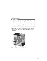
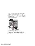


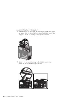
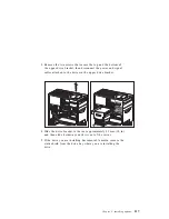
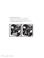

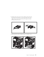
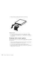
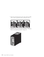
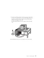


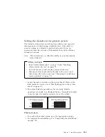

1. Determine which drive bay of the upper drive bracket you are
going to use.
2. Remove the upper drive bracket. See “Accessing drive bays” on
page 115.
3. Touch the static-protective package containing the new drive to
any unpainted (bare) metal surface and then remove the drive.
4. Install the drive into the upper drive bracket so that the power
and signal cable connectors are to the rear of the server. Align
the screw holes and insert the four screws.
120
Netfinity 3500 M10 User's Handbook
Summary of Contents for Netfinity 3500 M10
Page 1: ...Netfinity 3500 M10 User s Handbook...
Page 2: ......
Page 3: ...Netfinity 3500 M10 User s Handbook IBM...
Page 14: ...xii Netfinity 3500 M10 User s Handbook...
Page 18: ...xvi Netfinity 3500 M10 User s Handbook...
Page 80: ...62 Netfinity 3500 M10 User s Handbook...
Page 228: ...210 Netfinity 3500 M10 User s Handbook...
Page 236: ...System board switches 218 Netfinity 3500 M10 User s Handbook...
Page 256: ...238 Netfinity 3500 M10 User s Handbook...
Page 267: ......
Page 268: ...IBM Part Number 37L6687 Printed in U S A July 1999 37L6687...