


20. 50 MHz Voltage-Tuned Oscillator Adjustments
14. Adjust All POS SUPPLY
for a DVM indication the same as
that noted in step 12. See Figure 3-79 for location of adjustment.
High-Frequency
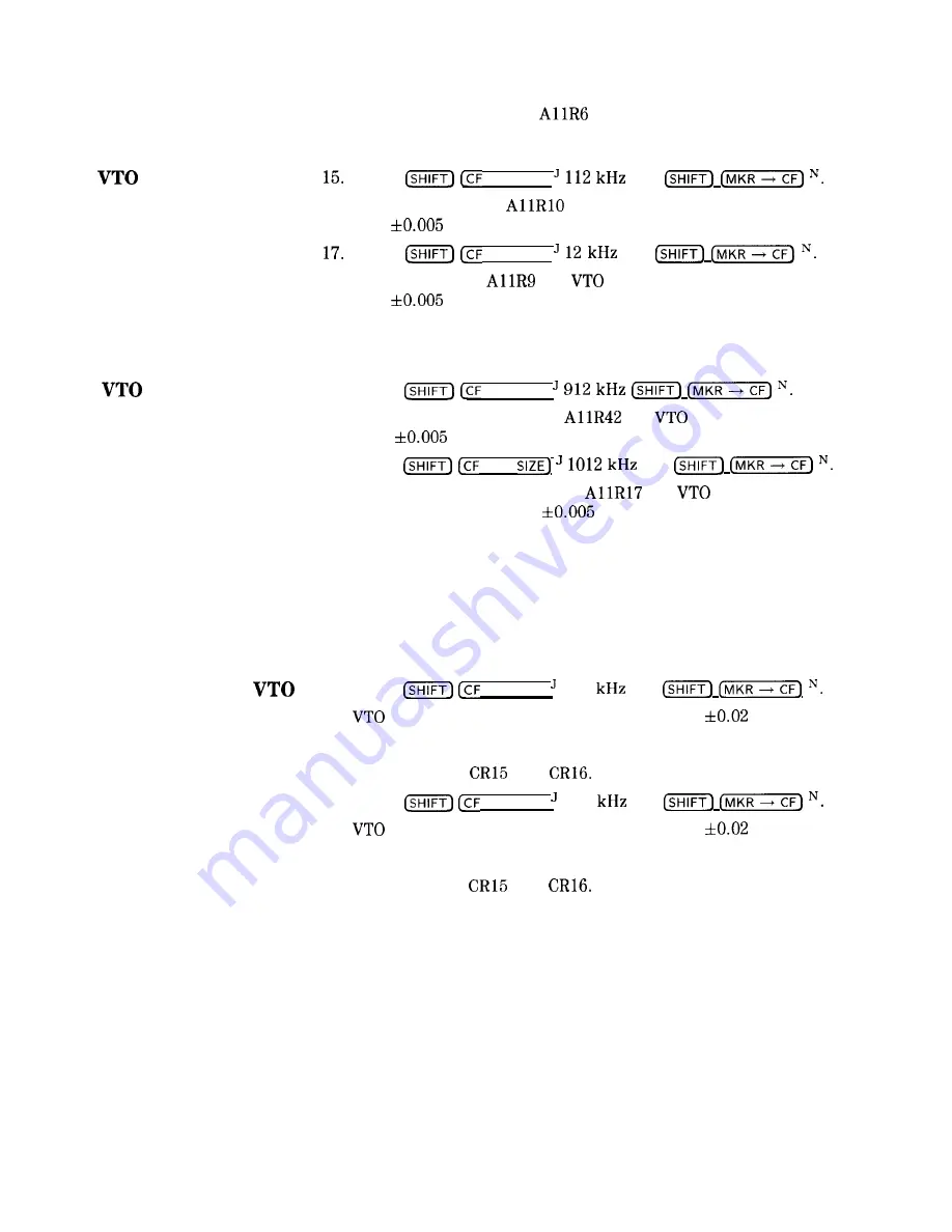
Key in
STEP SIZE
]
and
End Adjustment
16. Adjust All OFFSET
for VTP frequency indication 28.000
MHz
MHz.
Key in
STEP SIZE
)
and
18. Adjust All GAIN
for
frequency indication of 28.750
MHz
MHz.
19. Repeat steps 15 through 18 until specifications of steps 16 and 18
are achieved.
Low-Frequency
20.
Key in
STEP SIZE
]
End Adjustment
21. Adjust All SHAPING ATTN
for
indication of 22.000
MHz
MHz. See Figure 3-78 for location of adjustment.
22.
Key in
STEP
and
23. Adjust All SHAPING OFFSET
for
frequency
indication of 21.250 MHz
MHz. See Figure 3-78 for
location of adjustment.
24. Repeat steps 21 through 23 until specifications of steps 20 and 23
are achieved.
25. Go back to step 15 and repeat both High-Frequency End and
Lo-Frequency End adjustments until specifications of both
(contained in steps 16, 18, 21, and 23 are achieved.
26.
Key in
STEP SIZE
)
512
and
Center-Frequency
27.
frequency indication should be 25.00 MHz
MHz. If
Checks
it is not, and specifications of steps 16, 18, 21, and 23 are met,
a malfunction is indicated. The most likely suspects would be
varactor diodes
and
28.
Key in
STEP SIZE
]
612
and
29.
frequency indication should be 24.25 MHz
MHz. If
it is not, and specifications of steps 16, 18, 21, and 23 are met,
a malfunction is indicated. The most likely suspects would be
varactor diodes
and
30. Set LINE switch to STANDBY.
31. Replace Al1 50 MHz Voltage-Tuned Oscillator in instrument
without extenders and replace screws in cover.
3-132 Adjustments
Summary of Contents for 8568B
Page 13: ...6 7 IF Section Bottom View 6 10 Contents 7 ...
Page 19: ......
Page 37: ......
Page 42: ......
Page 48: ......
Page 53: ......
Page 61: ......
Page 90: ......
Page 106: ...Test 13 Average Noise Level Test 2 84 Performance Tests ...
Page 162: ......
Page 224: ......
Page 268: ......
Page 270: ......
Page 272: ......
Page 278: ......
Page 312: ...AlVl Figure 6 6 IF Section Front View w3 w9 Major Assembly and Component locations 6 9 ...