Installation manual.
CNC 8060
CNC 8065
15.
HARD
WARE.
N
u
mber th
e digi
ta
l
inpu
ts and
o
u
tp
uts
o
f th
e CANope
n bus.
·660·
(R
EF
: 1709)
15.5
Number the digital inputs and outputs of the CANopen bus.
By default, the CNC numbers the digital inputs sequentially, according to the order of the
modules in the bus. When the bus is CANopen, the CNC allows the digital I/O nodes in logic
blocks (virtual modules) to be divided, and then to establish the numbering of the I/Os of each
logic block, assigning a base index to the first one.
• In RIO5 and RIOR nodes, each module is a logic block, several modules cannot be
grouped in a block or divide a module into blocks. The logic blocks must have the same
number and size as the modules physically detected in the bus.
• In the RIO5 nodes, each double module (module with two boards) it counts as two, in
other words, two logic blocks.
• In RIOW nodes and third-party nodes, it is possible to display as many logic blocks as
desired, both in number and in size.
Configure the digital inputs.
The digital inputs and outputs are configured via machine parameters.
The configuration must meet the following requirements. If the parameters are not set
according to these requirements, the CNC will ignore it and it will number the digital inputs
sequentially according to the order of the modules in the bus.
• The parameters of all I/O nodes of the bus must be set; no node can be left undefined.
• The parameters of all the resources of a node must be set; no I/O can be left without a
number.
• The maximum number of logic blocks in the system will be 64, both for digital inputs and
digital outputs.
• The number of I/Os in a logic block must be other than zero and a multiple of 8 (8, 16,
24, 32, ...1024).
• The values of the base index must be comply with the formula "8n + 1" (i.e. 1, 9, 17, 25,
etc.).
• The blocks may be distributed at will within the range of resources managed by PLC
(1...1024). The PLC admits blanks, but the blocks cannot overlap; in other words, a PLC
digital input or output can only belong to a single node-module of the bus.
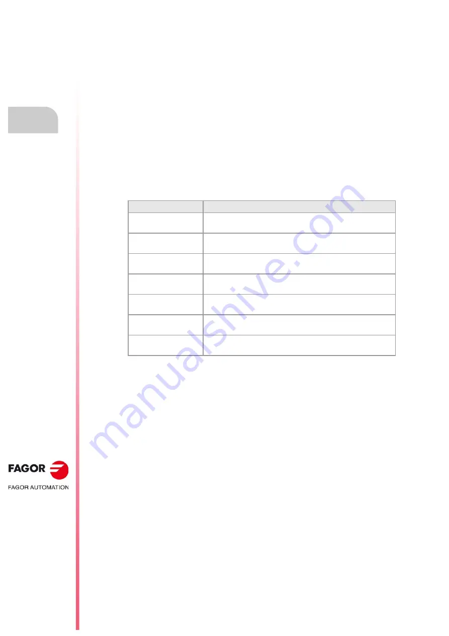
Parameter.
Meaning.
NDIMOD
Total number of digital input logic blocks.
Possible values: From 0 to 42 (by default; 0).
DIMODADDR
Base addresses of the digital input logic blocks.
MNEMONIC
Mnemonic of the logic block.
NODE
Node number of the header to which the logic block belongs.
Possible values: From 1 to 126 (by default; 0).
BLOCK
Number of the logic block.
Possible values: From 1 to 64 (by default; 0).
ADDRESS
Base address of the logic block.
Possible values: From 1 to 1017 (by default, the first valid value).
NDI
Number of digital inputs of the module.
Possible values: From 8 to 1024 (by default; 0).
Summary of Contents for CNC 8060
Page 1: ...Ref 1709 8060 8065 CNC Installation manual...
Page 10: ...BLANK PAGE 10...
Page 14: ...BLANK PAGE 14...
Page 20: ...BLANK PAGE 20...
Page 32: ...BLANK PAGE 32...
Page 36: ...BLANK PAGE 36...
Page 38: ...BLANK PAGE 38...
Page 40: ...BLANK PAGE 40...
Page 41: ...PART 1 INSTALLATION MANUAL...
Page 42: ...BLANK PAGE 42...
Page 532: ...Installation manual CNC 8060 CNC 8065 9 CNC VARIABLES 532 REF 1709...
Page 533: ...PART 2 CONCEPTS...
Page 534: ...BLANK PAGE 534...
Page 548: ...Installation manual CNC 8060 CNC 8065 10 GENERAL SETUP Configuration examples 548 REF 1709...
Page 644: ...Installation manual CNC 8060 CNC 8065 14 SUBROUTINES Assistance for subroutines 644 REF 1709...
Page 668: ...Installation manual CNC 8060 CNC 8065 15 HARDWARE Configure the PT100 inputs 668 REF 1709...
Page 697: ...Installation manual CNC 8060 CNC 8065 697 User notes REF 1709...


