Installation manual.
CNC 8060
CNC 8065
4.
PLC PROGRAMMIN
G
.
Dire
c
tin
g
instructi
ons.
·344·
(R
EF
: 1709)
Understanding how real and image values work.
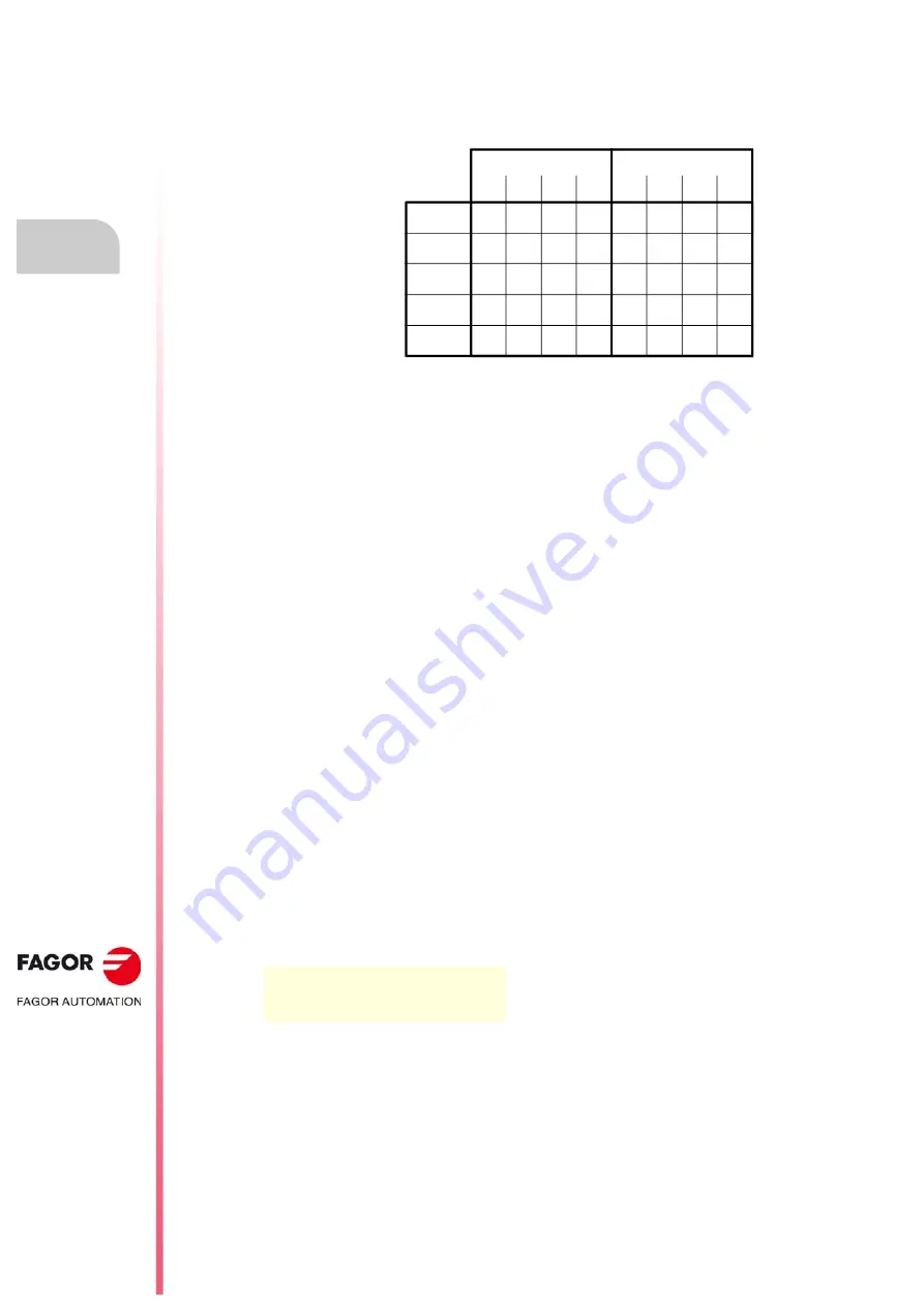
The following example shows how the PLC acts when working with real or image values.
For the given PLC program and with the resources initialized to zero, it shows the status of
all the resources at the end of each scan or cycle.
With real values (REA), output O5 goes high (=1) at the end of the first cycle scan, whereas
it needs 4 cycle scans when using image values (IMA).
In the first cycle, ()=M1 sets the real value of M1=1, but its image value is ·0·. Only at the
end of this cycle scan will it be ·1·.
The system is faster when working with real values (REA); whereas with image values (IMA),
it is possible to analyze the same resource throughout the whole program with the same
value, regardless of its current value.
L
Label.
It is used to identify a program line. It may be defined in two ways:
• With L followed by up to 7 digits (L1 - L9999999).
• With L_ followed by 8 characters (L_GEAR).
If it is defined within a module (CY1, PRG or PE), it identifies a program line and allows
making references or jumps.
If it is defined outside the modules, for example at the end of the program after END, it
indicates the beginning of a subroutine. It is the same as the SUB directing instruction.
If a program has more than one label with the same name or number, the PLC program will
issue the corresponding error message when generating the executable program.
SUB
Subroutine definition.
It indicates the beginning of a subroutine. A subroutine is a portion of the program that may
be called upon by any executable instruction.
It is defined with SUB followed by a blank space and up to 24 characters. A subroutine must
always end with an END instruction.
They must be defined outside the modules (PRG, CY1, PE), for example at the end of the
program after the directing instruction END.
A subroutine can also start with the L instruction and end with the END instruction.
SUB A22
···
END
Scan 1
Scan 4
Scan 3
Scan 2
M1 M2 M3 O5
M1 M2 M3 O5
1
1
1
1
1
1
1
1
1
1
1
1
1
1
1
0
1
1
1
1
1
1
0
0
1
1
1
1
1
0
0
0
0
0
0
0
0
0
0
0
REA
IMA
()=M1
M3 = O5
M2 = M3
M1 = M2
Summary of Contents for CNC 8060
Page 1: ...Ref 1709 8060 8065 CNC Installation manual...
Page 10: ...BLANK PAGE 10...
Page 14: ...BLANK PAGE 14...
Page 20: ...BLANK PAGE 20...
Page 32: ...BLANK PAGE 32...
Page 36: ...BLANK PAGE 36...
Page 38: ...BLANK PAGE 38...
Page 40: ...BLANK PAGE 40...
Page 41: ...PART 1 INSTALLATION MANUAL...
Page 42: ...BLANK PAGE 42...
Page 532: ...Installation manual CNC 8060 CNC 8065 9 CNC VARIABLES 532 REF 1709...
Page 533: ...PART 2 CONCEPTS...
Page 534: ...BLANK PAGE 534...
Page 548: ...Installation manual CNC 8060 CNC 8065 10 GENERAL SETUP Configuration examples 548 REF 1709...
Page 644: ...Installation manual CNC 8060 CNC 8065 14 SUBROUTINES Assistance for subroutines 644 REF 1709...
Page 668: ...Installation manual CNC 8060 CNC 8065 15 HARDWARE Configure the PT100 inputs 668 REF 1709...
Page 697: ...Installation manual CNC 8060 CNC 8065 697 User notes REF 1709...


