By default the importation wizard allocates 2,500 grid cells to each site based on dimensions. If you have a site that
is 250 ft. by 100 ft, the Floor Plan importation wizard would calculate the grid cell size at 10 feet. 250 ft. x 100 ft.
= 25,000 ft. 25,000 ft. / 2,500 ft. = 10 ft.
NOTE: Decreasing the grid cell size will increase accuracy, but it also increase CPU consumption by the floor caching threads and
the location caching threads. Check the
System > Performance
page to ensure your server is functioning properly when you make a
change to this setting.
Other items worth noting:
l
If this is a CAD file, then the Floor Plan creation wizard will automatically inherit height and width from the
drawing.
l
If this is a non-CAD file, then the height and width is zero.
l
CAD files are converted to a JPG with a resolution of 4096 horizontal pixels at 100% quality prior to cropping. If
you crop, then you will lose clarity.
l
CAD files must be generated from AutoCAD and may not exceed 10 MB.
l
Metric CAD files are supported.
l
Importing GIF files for floor plans can result in blank QuickView thumbnails.
Sizing a Non-CAD Floor Plan
You should not have to resize a CAD drawing unless you see nonsensical dimensions. To resize a non-CAD image if
you already know the dimensions, follow these steps:
1. Select the
Manually Measure Floor
button in the
Dimensions
section. The pointer changes to a cross-hair icon.
2. Locate two points within the floor plan that you know the distance. Most door jams (door openings) are 3 feet.
3. Select and hold to establish the first point and drag your mouse to the second point and release.
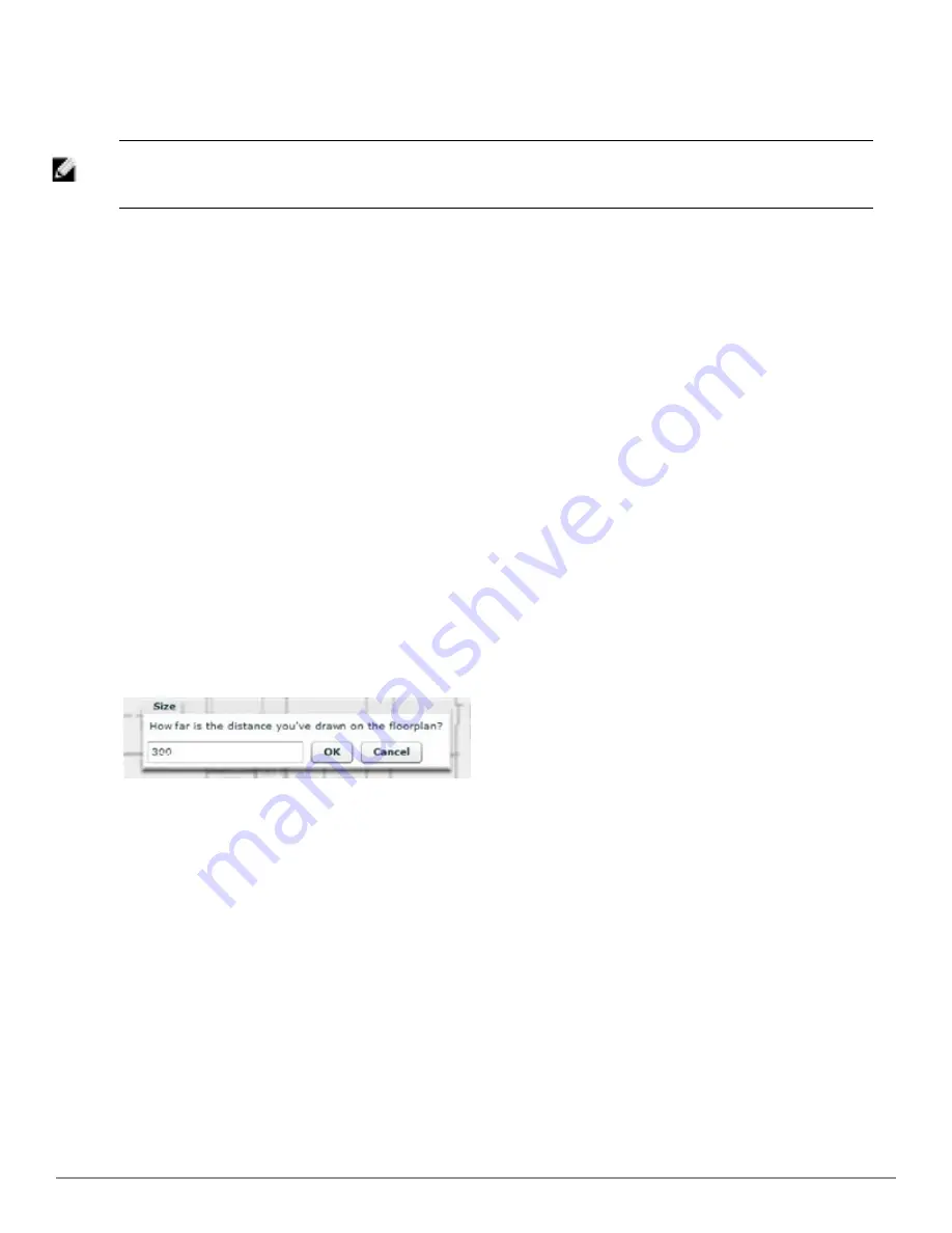
4. A distance dialogue box appears. Enter the proper length in feet, as shown in
Figure 233
.
Figure 233:
Manually Measuring a Floor Plan
5. Select
OK
.
Floor plans can be resized in VisualRF after they have been uploaded. Within VisualRF you will also be able to zoom
in on a room or doorway to increase the accuracy of your sizing.
Removing Color from a Floor Plan Image
To remove color, locate the
Image Manipulation
section and select
B&W
in the
Image
field.
Assigning Campus, Building and Floor Numbers
Locate the
Floor Info
Section and assign the following information, as detailed in
Table 147
and illustrated in
Figure 234
:
Dell PowerConnect W-AirWave 7.6 | User Guide
Using VisualRF | 299
Summary of Contents for PowerConnect W-AirWave 7.6
Page 1: ...Dell PowerConnect W AirWave 7 6 User Guide ...
Page 12: ...xii Dell PowerConnect W AirWave 7 6 User Guide ...
Page 112: ...100 Configuring and Using Device Groups Dell PowerConnect W AirWave 7 6 User Guide ...
Page 162: ...150 Discovering Adding and Managing Devices Dell PowerConnect W AirWave 7 6 User Guide ...
Page 198: ...186 Using RAPIDS and Rogue Classification Dell PowerConnect W AirWave 7 6 User Guide ...
Page 276: ...264 Creating Running and Emailing Reports Dell PowerConnect W AirWave 7 6 User Guide ...
Page 324: ...312 Using VisualRF Dell PowerConnect W AirWave 7 6 User Guide ...
Page 332: ...320 Index Dell PowerConnect W AirWave 7 6 User Guide ...


