Chapter 1
1-124
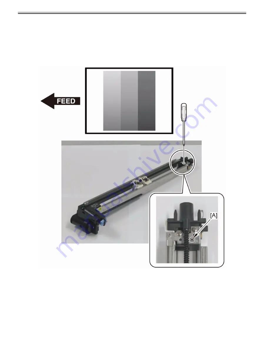
6-1) Turn the plastic screw [A] clockwise to make a full round.
Refer to the replacement procedure of the Primary Charging Assembly to install the Primary Charging Assembly to the Host Machine, and then output the test print
to check the image.
6-2) If the image at the front side of test print image is still dark, turn the plastic screw [A] clockwise to make another full round.
Refer to the replacement procedure of the Primary Charging Assembly to install the Primary Charging Assembly to the Host Machine, and then output the test print
to check the image.
6-3) If the image at the front side of the test print is still dark, turn the plastic screw [A] clockwise to make a half round.
Refer to the replacement procedure of the Primary Charging Assembly to install the Primary Charging Assembly to the Host Machine, and then output the test print
to check the image.
7) Adjust the Primary Charging Assembly (in the case of dark image at the rear side on the test print).
In the case of dark image at the rear side of the test print, execute step 7-1) through 7-3) below until the density gets even. Then, if there is no density unevenness,
execute the work in step 8) and later.
7-1) Turn the plastic screw [A] counterclockwise to make a full round.
Refer to the replacement procedure of the Primary Charging Assembly to install the Primary Charging Assembly to the Host Machine, and then output the test print
to check the image.
7-2) If the image at the rear side of the test print is still dark, turn the plastic screw [A] counterclockwise to make another full round.
Refer to the replacement procedure of the Primary Charging Assembly to install the Primary Charging Assembly to the Host Machine, and then output the test print
to check the image.
7-3) If the image at the rear side of the test print is still dark, turn the plastic screw [A] counterclockwise to make a half turn.
Refer to the replacement procedure of the Primary Charging Assembly to install the Primary Charging Assembly to the Host Machine, and then output the test print
to check the image.
8) Execute the ITB neutral position adjustment.
Service Mode > COPIER > Function > INSTALL > INIT-ITB (Creation of ITB edge profile)
9) Execute the auto gradation adjustment.
Settings/Registration > Adjustment/Maintenance > Adjust Image Quality > Auto Adjust Gradation > Full Adjust
10) Execute the color displacement correction.
Settings/Registration > Adjustment/Maintenance > Adjust Image Quality > Auto Correct Color Mismatch
Summary of Contents for imagePRESS C800 Series
Page 1: ...Dec 2 2014 Troubleshooting Guide imagePRESS C800 Series...
Page 2: ......
Page 6: ......
Page 8: ......
Page 9: ...Chapter 1 Correcting Faulty Images...
Page 10: ......
Page 14: ......
Page 114: ...Chapter 1 1 100 7 2 Select the envelope type press OK...
Page 165: ...Chapter 1 1 151 3 Pull the Tray all the way out...
Page 167: ...Chapter 1 1 153 5 Remove the Waste Toner Container...
Page 172: ...Chapter 1 1 158 2 Pull out the staple cartridge holding it by the green tab...
Page 180: ...Chapter 1 1 166 5 Push in the new staple case until it clicks to insert it...
Page 181: ...Chapter 1 1 167 6 Close the Cover for the saddle stitch staple cartridge...
Page 199: ...Chapter 1 1 185 b 1 Take out the Waste Toner Container 1...
Page 201: ...Chapter 1 1 187 b 2 Install the Waste Toner Joint 1 to the Waste Toner Container 2...
Page 206: ...Chapter 1 1 192 b 9 Remove the Prism 1 1 Screw 2 1 Hook 3...
Page 207: ...Chapter 1 1 193 b 10 Clean the toner adhered to the 2 A parts on the prism...
Page 208: ...Chapter 1 1 194 b 11 Clean the toner adhered to the A part of the Waste Toner Container...
Page 210: ...Chapter 1 1 196 2 Pull out the punch waste tray...
Page 217: ...Chapter 1 1 203 3 Discard the staple waste...
Page 239: ...Chapter 1 1 225 3 Press Memory Media 4 Select the target memory media...
Page 250: ...Chapter 1 1 236 Select Share files and folders using SMB Windows Select the account to be used...
Page 255: ...Dec 2 2014...
Page 256: ......


