AC90 TENSION CONTROL FREQUENCY INVERTER MANUAL
Function Parameter specifications
133
6: RS485 communication
7: Optional card
8: Terminal selection PID giving is selected by multifunction input terminal combine which is set by
[F2.00-F2.07]
.
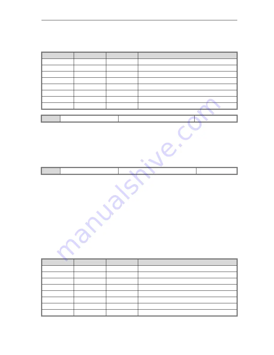
Terminal switch table:
Terminal 3
Terminal 2
Terminal 1
PID giving terminal switch selection
OFF OFF
OFF
Keyboard number give PID
OFF OFF
ON
Keyboard potentiometer
OFF ON
OFF
Terminal VS1 voltage analog
OFF ON
ON
Terminal VS2 voltage analog
ON OFF
OFF
Terminal AS current analog
ON OFF
ON
Terminal PUL pulse signal
ON ON
OFF
RS485 communication
ON ON
ON
Optional card
Fb.01
Keyboard number give PID
Setting range: 0.00-100.0%
Factory set: 50.0%
This function is valid only when
[Fb.00]
/
[Fb.02]
is set as keyboard mumber given/feedback. It is based on feedback
signal max range
[Fb.04]
. After this parameter is changed, PID given in monitor object is modified automatical at the
same time.
If
[Fb.04]
LED “0” is set as 3, this value can be modified by UP/DW key. Whether save the modification is decided by
[F4.04]
LED “00” digit.
Fb.02
PID feedback signal source
Setting range:0-8
Factory set:2
Set PID feedback signal input channel.
0: Keyboard number given PID
PID feedback channel decided by
[Fb.01]
.
1: Keyboard potentiometer
2: Terminal VS1 voltage analog
3: Terminal VS2 voltage analog
4: Terminal AS current analog
5: Terminal PUL pulse signal
6:RS485 communication
PID feedback channel decided by RS485.Communication address is H3009 or H2009.
7: Optional card
8: Terminal selection
PID feedback channel decided by multifunction input terminal combination. Multifunction input
terminal is set by
[F2.00-F2.07]
.
Terminal switch table:
Terminal 3
Terminal 2
Terminal 1
PID giving terminal switch selection
OFF OFF
OFF
Keyboard number give PID
OFF OFF
ON
Keyboard potentiometer
OFF ON
OFF
Terminal VS1 voltage analog
OFF ON
ON
Terminal VS2 voltage analog
ON OFF
OFF
Terminal AS current analog
ON OFF
ON
Terminal PUL pulse signal
ON ON
OFF
RS485 communication
ON ON
ON
Optional card
Note: PID controller given signal source and PID controller feedback signal source can not be the same
channel. Otherwise PID can not work normally.


