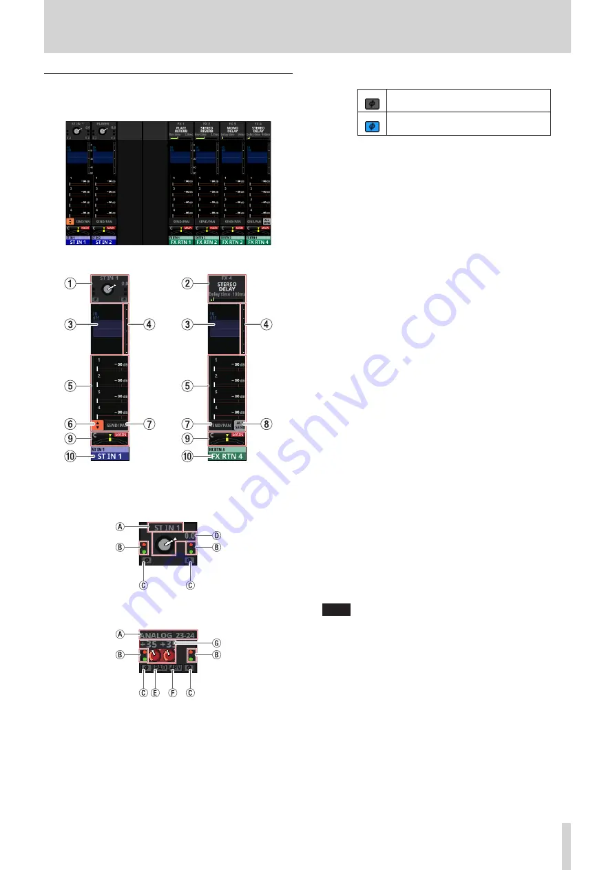
2 - Names and Functions of Parts
ST IN 1–2/FX RTN 1–4 Module Home
Screen
ST IN 1–2/FX RTN 1–4 Module Home Screen
ST IN 1–2/FX RTN 1–4 Module Home Screen details
1
INPUT area
o
This shows the input settings of the selected input source.
Input area display when the input source is not “ANALOG” or “SB-
16D connected by built-in Dante”
Input area display when the input source is “ANALOG” or “SB-16D
connected by built-in Dante”
a
This shows the input source name.
b
These indicators appear to light as shown below
depending on the input level.
Red: −3 dBFS, Green: −40 dBFS
c
This shows the input signal phase setting status.
Normal
Reversed
d
A D.TRIM knob and the digital trim value will be shown
when the input source of the selected module is not
“ANALOG” or “SB-16D connected by built-in Dante”.
e
This shows the −20dB pad setting status when the input
source of the selected module is “ANALOG” or “SB-16D
connected by built-in Dante”. When on, the icon will
appear highlighted.
f
This shows the phantom power (+48V) setting status
when the input source of the selected module is
“ANALOG” or “SB-16D connected by built-in Dante”.
When on, the icon will appear highlighted.
g
When the input source of the selected module is
“ANALOG” or “SB-16D connected by built-in Dante”,
this will show 2 analog gain knobs and the input level
values of the unit or SB-16D MIC/LINE input jacks.
o
Tap this area to show the selection frame. When the
selection frame is shown, corresponding LCD knobs can
be used to adjust the parameters shown.
o
When the selection frame is shown, tap this area to open
the MODULE (INPUT) Screen for the selected module. (See
“MODULE (INPUT) Screen” on page 87.)
2
FX area
o
This shows effects names and main effect parameters.
o
Tap this area to show the selection frame. When the
selection frame is shown, corresponding LCD knobs can
be used to adjust effect parameters shown.
o
When the selection frame is shown, tap this area to open
the MODULE (FX) Screen for the selected module. (See
“MODULE (FX) Screen” on page 90.)
3
EQ area
o
This shows a graph of the EQ frequency response.
o
Tap this area to open the MODULE (EQ) Screen for the
selected module. (See “MODULE (EQ) Screen” on page
4
Level meters
This shows the level of the signal at the set metering point.
(See “METERING POINT page” on page 34.) (See “ST IN 1–2
MODULE (OVERVIEW) Screens” on page 82.) (See “FX RTN
1–4 MODULE (OVERVIEW) Screens” on page 84.)
NOTE
i
The ST IN 1–2/FX RTN 1–4 modules are stereo, so stereo level
meters are shown.
i
When a level overload occurs, the entire bar meter will light
red.
i
The OVER indicator at the top of the level meter will appear
to light red when the level reaches or exceeds −0.00026 dBFS
(16-bit full-scale value).
TASCAM Sonicview 16/Sonicview 24
17


