6 – Modules
w
Analog GAIN knobs
o
When the input source of the selected module is
“ANALOG” or “SB-16D connected by built-in Dante”, this
will show analog gain knobs for each channel of this unit
or the SB-16D. These can be used to adjust input levels of
MIC/LINE input jacks.
Turn LCD knob 1 (lit red) to adjust it.
When Analog Reference Level = +6 dBu
PAD button setting
Range
OFF
+3 (default) – +57
ON
−17 – +37
When Analog Reference Level = +4 dBu
PAD button setting
Range
OFF
+12 (default) – +66
ON
−8 – +46
When Analog Reference Level = 0 dBu
PAD button setting
Range
OFF
+8 (default) – +62
ON
−12 – +42
o
These indicators appear to light as shown below
depending on the input level.
Red: −3 dBFS, Green: −40 dBFS
o
When the input source of the selected module is
“ANALOG” or “SB-16D connected by built-in Dante”, 2
Analog GAIN knobs will be shown together.
Turn LCD knob 1 (lit red) to adjust both together.
To operate them separately, turn the GANG function OFF
on the MODULE (INPUT) screen.
NOTE
Explanation of Analog GAIN values
When signals at the Analog Reference Level (+6 dBu, +4 dBu,
0 dBu) are input, the Analog GAIN value that becomes the
Digital Reference Level (−9 dBFS, −14 dBFS, −16 dBFS, −18
dBFS, −20 dBFS) at the digital stage is shown as “0”.
e
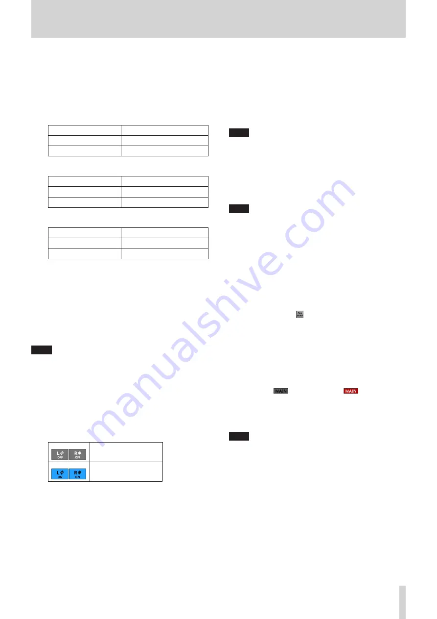
Phase buttons
Use these to change the phases of the signals for the selected
module.
Tap these buttons to reverse the phases of the selected
module signals.
Normal
Reversed
r
D.TRIM knob
Use this to adjust the digital trim value.
Range: -50.0 dB - +20.0 dB (default: 0.0 dB)
Turn LCD knob 3 (lit red) to adjust it.
t
MUTE button
Tap this button to turn muting on/off for the selected
module signal.
When MUTE is on, the button will be highlighted.
NOTE
The MUTE keys on the top of the unit can also be used to set
this.
y
FADER LEVEL
Use this to adjust the FADER level of the selected module
signal.
Range: - ∞ dB - +10.0 dB (default: - ∞ dB)
Turn LCD knob 7 (lit blue) to adjust it.
NOTE
i
The channel faders on top of the unit can also be used for
this adjustment.
i
Tap the area while pressing the HOME key on the top panel
to set the FADER level to 0 dB.
u
SENDS button
Tap this button to open the MODULE (SEND/PAN) Screen for
the selected module. (See “MODULE (SEND/PAN) Screen” on
i
MIX/FX SEND level indicators
o
This list shows the on/off and PRE/POST states and the
send levels to the MIX 1–22 and FX 1–4 buses. (See “8
ALL SEND button ( )” on page 18.)
o
Tap this area to open the MODULE (SEND/PAN) Screen for
the selected module with the bus selected for the tapped
area.
o
BAL
o
This adjusts the balance of the signals sent to the MAIN
L/R bus. Turn LCD knob 8 (lit yellow) to adjust it.
Range: L100 – C – R100 (default: C)
o
When the
icon is highlighted (
), signals are
being sent to the MAIN L/R bus.
o
Tap this area to open the MODULE (SEND/PAN) Screen for
the selected module. (See “MODULE (SEND/PAN) Screen”
NOTE
Tap this area while pressing the HOME key on the top panel
to set the balance to center (C).
TASCAM Sonicview 16/Sonicview 24
83


