2 - Names and Functions of Parts
3
MUTE keys and indicators
o
These mute/unmute modules assigned to the selected
layer.
o
When a MUTE key is on (lit), the signal of the
corresponding module is muted.
o
Depending on the DCA or Mute Group, the key will blink
when muted.
4
SOLO keys and indicators
o
These turn soloing on/off for modules assigned to the
selected layer.
o
When these keys are on (lit), the signals of the
corresponding modules will be sent to the SOLO L/R bus.
o
The keys will blink if soloing is on because of DCA.
NOTE
The MONITOR SETUP screen MONITOR/SOLO page, which is
where various solo settings can be made, can be opened by
pressing this key while pressing the MENU key. (See “Making
monitor output and solo function settings” on page 50.)
(See “12 – List of shortcut operations” on page 168.)
5
SEL keys and indicators
o
Press these keys to open the MODULE Screens
for modules assigned to the selected layer. The
corresponding keys light. If the MODULE Screen shown
for a module has been changed on the touchscreen, the
corresponding SEL key will light.
o
When a lit SEL key is pressed, the MODULE screen for
that module will be shown on the touchscreen that
corresponds to that SEL key if it is not already shown.
If the MODULE screen for that module is shown on the
touchscreen that corresponds to that SEL key, it will close
and the SEL key will become unlit.
NOTE
Pressing one of these keys while pressing the HOME key will
set the fader level for the corresponding module to 0 dB.
(When Sends On Fader mode is on, the SEND level will be set
instead.) (See “12 – List of shortcut operations” on page 168.)
6
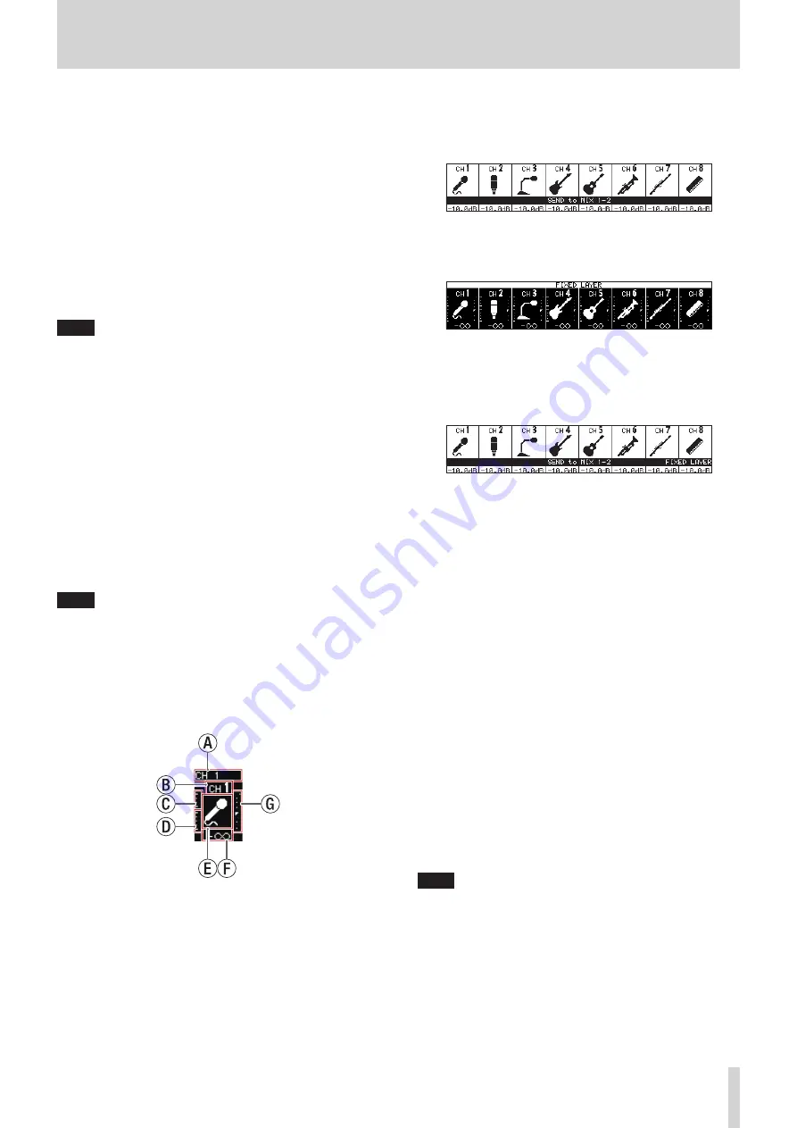
Channel screen
o
These show the following information for modules
assigned to the selected layer.
a
Module name
b
User module name (name set by user)*
c
GATE/EXP/DE-ESSER gain reduction meter
d
COMP/DUCKER gain reduction meter
e
Module icon*
f
Fader level value
g
Module meter (shows signal level of set metering point)
* See “MODULE NAME screen” on page 122 for details
about setting user module names and module icons.
o
When the SENDS ON FADER key is on (Sends On Fader
mode is on), the black and white display is inverted and
“SEND to [bus name]” will be shown on a black band at the
bottom of the screen.
o
When the FIX LAYER key (
s
) has been used to lock 8
channels to the layer, “FIXED LAYER” will be shown on a
white band at the top of the screen.
o
When the Sends On Fader mode is on and 8 channels
have been locked to the layer, the black and white display
will be inverted and “SEND to [bus name]” and FIXED
LAYER” will be shown on a black band at the bottom of the
screen.
o
Use the PREFERENCES Screen to set the brightness and
contrast of the channel screens. (See “PREFERENCES
7
Channel color bars
These show the colors set for the modules assigned to the
selected layer. (See “Changing set module colors” on page
8
Channel faders
o
When the SENDS ON FADER key is off (Sends On Fader
mode is off), these adjust the fader levels for the modules
assigned to the selected layer.
o
When the SENDS ON FADER key is on (Sends On Fader
mode is on), these adjust the send levels to the selected
bus for the modules assigned to the selected layer.
9
Output meters
These are output meters for the MAIN L/R bus.
The OVER indicators light red when they reach or exceed
−0.00026 dBFS (16-bit full-scale value).
0
HOME key
o
When the Menu Screen or a settings screen is open, press
to return to the Home Screen on all touchscreens.
o
Press and hold this key and the MENU key together for
5 seconds to open the LOCK SETUP screen. (See “LOCK
NOTE
Various shortcut operations are possible using this key
in combination with others. See “12 – List of shortcut
operations” on page 168 for details.
TASCAM Sonicview 16/Sonicview 24
7


