4 - 8
MELSEC-A
4 INSTALLATION, WIRING AND MAINTENANCE OF THE PRODUCT
4.3 Wiring
The wiring precautions for the AD75 are described below. Be careful to observe the
following items together with the "Handling precautions" described in section 4.1.3.
4.3.1 Precautions for wiring
(1)
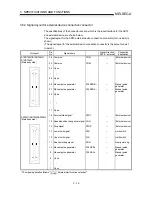
Perform wiring of the AD75 correctly while checking the terminal arrangement.
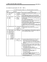
(For the terminal arrangement of the external device connection connector, refer
to section "3.5.2 Signal layout for external device connection connector.")
(2)
Solder or crimp the external device connection connector correctly.
An improperly soldered or crimped connector may cause malfunctions.
(3)
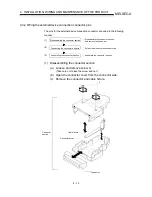
Be careful to avoid entry of chips, wiring dust and so on inside the AD75.
Otherwise fire, failure or malfunction may be caused.
(4)
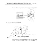
Be sure to install a cover for the external device connection connector if no
external device is connected. Otherwise malfunction may be caused.
(5)
Connect the external device connection connector, SSCNET connection
connector and peripheral device connection connector with the connector of the
AD75. Check that the connector snaps. An improperly connected connector will
cause poor continuity, possibly causing erroneous inputs or outputs.
(6)
Do not pull the cable when removing the cable from the AD75 or servo amplifier.
Hold and pull the connector connected to the AD75 or servo amplifier. If the cable
connected to the AD75 or servo amplifier is pulled, a malfunction may be caused.
As well, the AD75, servo amplifier or cable may be broken.
(7)
Disconnect the external device connection connector and SSCNET connection
connector when the system is stopped.
If the external device connection connector or SSCNET connection connector is
disconnected during operation of the system, the system will be stopped.
(8)
Route the cables connected to the AD75, in a duct, or fix them. If cables are not
routed in the duct or no fixing measures are taken to them, drifting or moving
cables, breakage of the AD75, servo amplifier or cable due to a carelessly pulled
cable, or malfunction caused by a poorly connected cable may be caused.
(9)
Do not tie the AD75 cable with the main circuit cable, power cable, or a load
cable for other than the programmable logic controller or do not route the AD75
cable near them. Separate these by 100 mm as a measure. Otherwise noise,
surge or induction may cause a malfunction.
(10) When routing the AD75 cable near a power cable at a distance smaller than 100
mm, use a shielded cable for a countermeasure against noise. Connect the
shielding wire of the shielded cable securely to the panel of the AD75.
Содержание A1SD75M1
Страница 2: ......
Страница 20: ...A 18 MEMO...
Страница 22: ...MEMO...
Страница 27: ...1 5 MELSEC A 1 PRODUCT OUTLINE MEMO...
Страница 42: ...1 20 MELSEC A 1 PRODUCT OUTLINE MEMO...
Страница 52: ...2 10 MELSEC A 2 SYSTEM CONFIGURATION MEMO...
Страница 111: ...5 21 MELSEC A 5 DATA USED FOR POSITIONING CONTROL MEMO...
Страница 115: ...5 25 MELSEC A 5 DATA USED FOR POSITIONING CONTROL MEMO...
Страница 123: ...5 33 MELSEC A 5 DATA USED FOR POSITIONING CONTROL MEMO...
Страница 127: ...5 37 MELSEC A 5 DATA USED FOR POSITIONING CONTROL MEMO...
Страница 167: ...5 77 MELSEC A 5 DATA USED FOR POSITIONING CONTROL MEMO...
Страница 193: ...5 103 MELSEC A 5 DATA USED FOR POSITIONING CONTROL MEMO...
Страница 276: ...5 186 MELSEC A 5 DATA USED FOR POSITIONING CONTROL MEMO...
Страница 332: ...7 18 MELSEC A 7 MEMORY CONFIGURATION AND DATA PROCESS MEMO...
Страница 334: ...MEMO...
Страница 422: ...9 64 MELSEC A 9 MAIN POSITIONING CONTROL MEMO...
Страница 446: ...10 24 MELSEC A 10 ADVANCED POSITIONING CONTROL MEMO...
Страница 472: ...11 26 MELSEC A 11 MANUAL CONTROL MEMO...
Страница 576: ...12 104 MELSEC A 12 CONTROL AUXILIARY FUNCTIONS MEMO...
Страница 673: ...Appendix 5 MELSEC A APPENDICES Axis address mm inch degree pulse Axis address mm inch degree pulse...
Страница 679: ...Appendix 11 MELSEC A APPENDICES Initial value Axis 1 Axis 2 Axis 3 Remarks 0 0 0 1 1 0 0 0 0 0 300 0 0 0...
Страница 683: ...Appendix 15 MELSEC A APPENDICES Initial value Axis 1 Axis 2 Axis 3 Remarks 0 0 1 0 0 50 80 0 0 980...
Страница 691: ...Appendix 23 MELSEC A APPENDICES Initial value Axis 1 Axis 2 Axis 3 Remarks 0 0 0 0 0 50 80 0 0 0 0 0 980 4000 0...
Страница 745: ......


