5 - 57
MELSEC-A
5 DATA USED FOR POSITIONING CONTROL
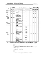
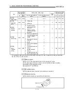
[Table 1]
Pr.1
setting value
Value set with peripheral device
(unit)
Value set with sequence program
(unit)
0 : mm
–214748364.8 to 214748364.7 (
µ
m)
–2147483648 to 2147483647 (
×
10
-1
µ
m)
1 : inch
–21474.83648 to 21474.83647 (inch)
–2147483648 to 2147483647 (
×
10
-5
inch)
2 : degree –21474.83648 to 21474.83647 (degree) –2147483648 to 2147483647 (
×
10
-5
degree)
3 : pulse
–2147483648 to 2147483647 (pulse)
–2147483648 to 2147483647 (pulse)
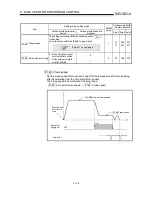
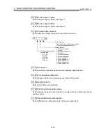
Pr.56 Zero point return torque limit value
Set the value to limit the servomotor torque after reaching the creep speed during
machine zero point return.
Refer to section "12.4.2 Torque limit function" for details on the torque limits.
Pr.57 Speed designation during zero point shift
Set the operation speed for when a value other than "0" is set for " Pr.55 Zero
point shift amount". Select the setting from " Pr.48 Zero point return speed" or
" Pr.49 Creep speed".
0 : Designate " Pr.48 Zero point return speed" as the setting value.
1 : Designate " Pr.49 Creep speed" as the setting value.
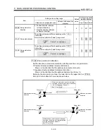
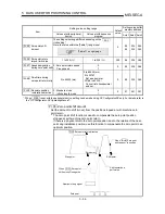
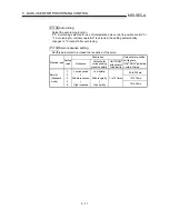
Pr.58 Dwell time during zero point return retry
When zero point return retry is validated (when "1" is set for Pr.50 ), set the stop
time after decelerating in 2) and 4) in the following drawing.
Start position
Temporarily stop for
the time set in Pr. 58
Temporarily stop for
the time set in Pr. 58
1)
2)
3)
4)
5)
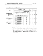
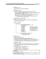
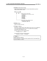
Pr.59
Absolute position restoration selection
In the absolute position detection system in the control unit "degree", set the mode
for absolute position restoration. Select either the standard mode or infinite length
mode for the setting.
0 : Standard mode
1 : Infinite length mode
Setting of other than "1" is regarded as "0", the standard mode.
After setting, turning the PLC READY signal [Y1D] from OFF to ON and making a
machine zero point return establishes the mode for absolute position restoration.
The established mode for absolute position restoration is stored into the axis
monitor " Md.121 Absolute position restoration mode".
For details of the mode for absolute position restoration, refer to section "12.6.2
Absolute position restoration mode switching function".
Содержание A1SD75M1
Страница 2: ......
Страница 20: ...A 18 MEMO...
Страница 22: ...MEMO...
Страница 27: ...1 5 MELSEC A 1 PRODUCT OUTLINE MEMO...
Страница 42: ...1 20 MELSEC A 1 PRODUCT OUTLINE MEMO...
Страница 52: ...2 10 MELSEC A 2 SYSTEM CONFIGURATION MEMO...
Страница 111: ...5 21 MELSEC A 5 DATA USED FOR POSITIONING CONTROL MEMO...
Страница 115: ...5 25 MELSEC A 5 DATA USED FOR POSITIONING CONTROL MEMO...
Страница 123: ...5 33 MELSEC A 5 DATA USED FOR POSITIONING CONTROL MEMO...
Страница 127: ...5 37 MELSEC A 5 DATA USED FOR POSITIONING CONTROL MEMO...
Страница 167: ...5 77 MELSEC A 5 DATA USED FOR POSITIONING CONTROL MEMO...
Страница 193: ...5 103 MELSEC A 5 DATA USED FOR POSITIONING CONTROL MEMO...
Страница 276: ...5 186 MELSEC A 5 DATA USED FOR POSITIONING CONTROL MEMO...
Страница 332: ...7 18 MELSEC A 7 MEMORY CONFIGURATION AND DATA PROCESS MEMO...
Страница 334: ...MEMO...
Страница 422: ...9 64 MELSEC A 9 MAIN POSITIONING CONTROL MEMO...
Страница 446: ...10 24 MELSEC A 10 ADVANCED POSITIONING CONTROL MEMO...
Страница 472: ...11 26 MELSEC A 11 MANUAL CONTROL MEMO...
Страница 576: ...12 104 MELSEC A 12 CONTROL AUXILIARY FUNCTIONS MEMO...
Страница 673: ...Appendix 5 MELSEC A APPENDICES Axis address mm inch degree pulse Axis address mm inch degree pulse...
Страница 679: ...Appendix 11 MELSEC A APPENDICES Initial value Axis 1 Axis 2 Axis 3 Remarks 0 0 0 1 1 0 0 0 0 0 300 0 0 0...
Страница 683: ...Appendix 15 MELSEC A APPENDICES Initial value Axis 1 Axis 2 Axis 3 Remarks 0 0 1 0 0 50 80 0 0 980...
Страница 691: ...Appendix 23 MELSEC A APPENDICES Initial value Axis 1 Axis 2 Axis 3 Remarks 0 0 0 0 0 50 80 0 0 0 0 0 980 4000 0...
Страница 745: ......


