14 - 4
MELSEC-A
14 TROUBLESHOOTING
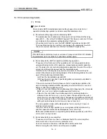
Error storage
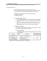
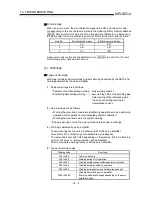
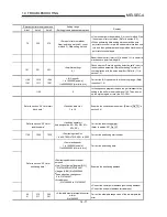
When an error occurs, the error detection signal turns ON, and the error code
corresponding to the error details is stored in the following buffer memory address
( Md.33 Axis error No.) for axis error No. storage. Note that there is a delay of up
to 56.8ms after the error detection signal turns ON until the error code is stored.
Axis No.
Error detection signal
Buffer memory address
1 XA
807
2 XB
907
3 XC
1007
A new error code is stored in the buffer memory ( Md.33 Axis error No.) for axis
error storage every time an error occurs.
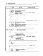
(2) Warnings
Types of warnings
Warnings include system warnings and axis warnings detected by the AD75 and
warnings detected by the servo amplifier.
(1) System warnings are as follows.
•
System control data setting warning ... Axis warning of axis 1.
•
Positioning data setting warning ......... Axis warning of the corresponding axis.
Axis warning of the reference axis in
the case of a setting warning for
interpolation control.
(2) Axis warnings are as follows.
•
Warning that occurred at operation start/during operation such as positioning
operation, JOG operation or manual pulse generator operation.
•
Warning that occurred due to the system warning.
If the axis warning occurs, the axis operation status does not change.
(3) Warnings detected by servo amplifier
These warnings occur due to a hardware fault of the servo amplifier,
servomotor, etc. or when any servo parameter is inadequate.
The servo does not switch OFF depending on the warning, but if it is left as-is,
an error will occur or normal operation will be disabled.
After removing the warning factor, reset the servo amplifier.
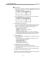
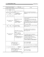
(4) Types of warning codes
Warning code
Error type
100 to 199
Common warning
300 to 399
Warning during JOG operation
400 to 499
Warning during manual pulse generator operation
500 to 599
Warning during positioning operation
900 to 999
Warning during system control data range check
2090 to 2999
Warning detected by servo amplifier
(Warning definition changes depending on the servo
amplifier model.)
Содержание A1SD75M1
Страница 2: ......
Страница 20: ...A 18 MEMO...
Страница 22: ...MEMO...
Страница 27: ...1 5 MELSEC A 1 PRODUCT OUTLINE MEMO...
Страница 42: ...1 20 MELSEC A 1 PRODUCT OUTLINE MEMO...
Страница 52: ...2 10 MELSEC A 2 SYSTEM CONFIGURATION MEMO...
Страница 111: ...5 21 MELSEC A 5 DATA USED FOR POSITIONING CONTROL MEMO...
Страница 115: ...5 25 MELSEC A 5 DATA USED FOR POSITIONING CONTROL MEMO...
Страница 123: ...5 33 MELSEC A 5 DATA USED FOR POSITIONING CONTROL MEMO...
Страница 127: ...5 37 MELSEC A 5 DATA USED FOR POSITIONING CONTROL MEMO...
Страница 167: ...5 77 MELSEC A 5 DATA USED FOR POSITIONING CONTROL MEMO...
Страница 193: ...5 103 MELSEC A 5 DATA USED FOR POSITIONING CONTROL MEMO...
Страница 276: ...5 186 MELSEC A 5 DATA USED FOR POSITIONING CONTROL MEMO...
Страница 332: ...7 18 MELSEC A 7 MEMORY CONFIGURATION AND DATA PROCESS MEMO...
Страница 334: ...MEMO...
Страница 422: ...9 64 MELSEC A 9 MAIN POSITIONING CONTROL MEMO...
Страница 446: ...10 24 MELSEC A 10 ADVANCED POSITIONING CONTROL MEMO...
Страница 472: ...11 26 MELSEC A 11 MANUAL CONTROL MEMO...
Страница 576: ...12 104 MELSEC A 12 CONTROL AUXILIARY FUNCTIONS MEMO...
Страница 673: ...Appendix 5 MELSEC A APPENDICES Axis address mm inch degree pulse Axis address mm inch degree pulse...
Страница 679: ...Appendix 11 MELSEC A APPENDICES Initial value Axis 1 Axis 2 Axis 3 Remarks 0 0 0 1 1 0 0 0 0 0 300 0 0 0...
Страница 683: ...Appendix 15 MELSEC A APPENDICES Initial value Axis 1 Axis 2 Axis 3 Remarks 0 0 1 0 0 50 80 0 0 980...
Страница 691: ...Appendix 23 MELSEC A APPENDICES Initial value Axis 1 Axis 2 Axis 3 Remarks 0 0 0 0 0 50 80 0 0 0 0 0 980 4000 0...
Страница 745: ......


