12 - 23
MELSEC-A
12 CONTROL AUXILIARY FUNCTIONS
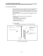
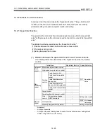
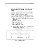
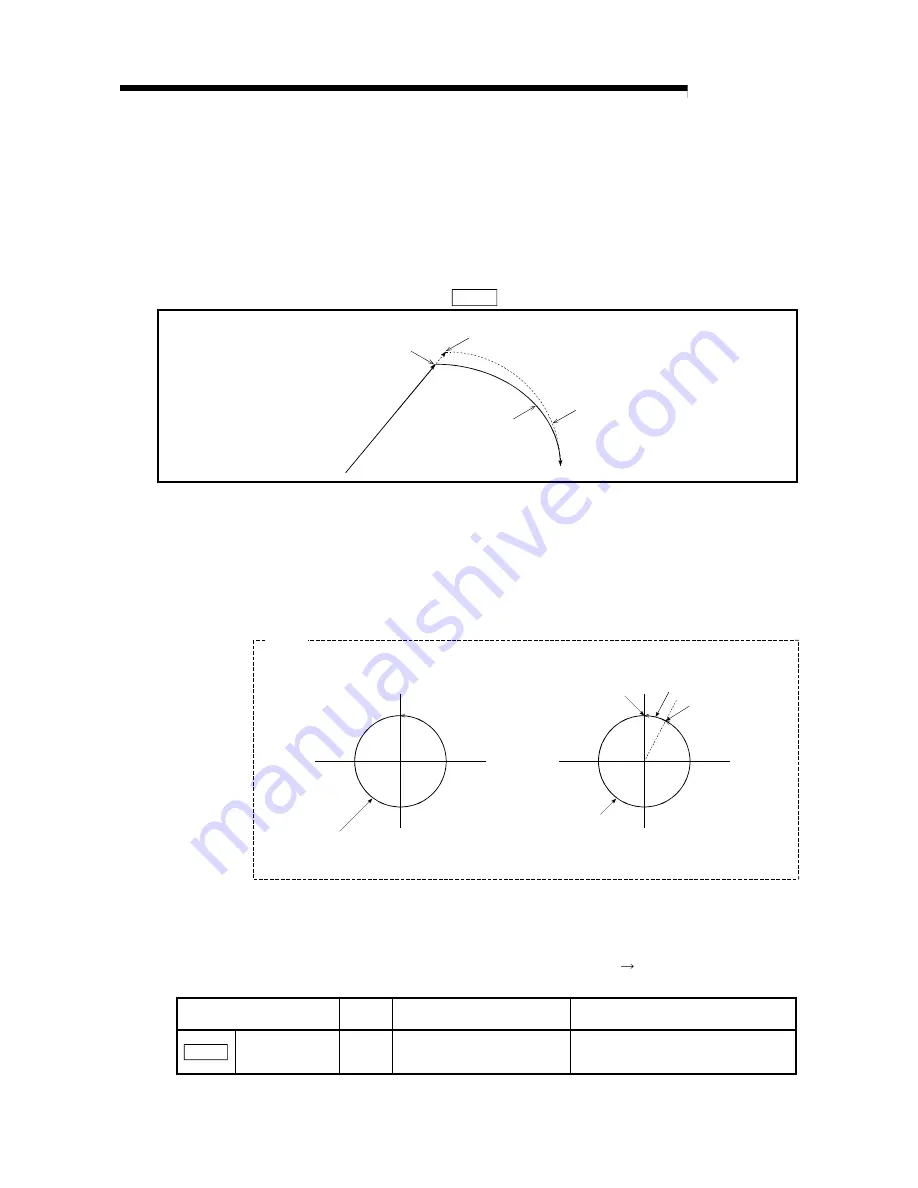
(c) When continuous path control of a circular interpolation is being carried out in
the near pass mode, an address in which the extra movement amount is
subtracted from the positioning address of the positioning data currently being
executed is replaced by the starting point address of the next positioning data
No.
Because of this, circular interpolation control cannot be carried out using the
increment system.
Because the starting point address will be replaced, an error "large arc error
deviation" (error code: 506) may occur.
In this case, adjust the " Pr.42 Allowable circular interpolation error width".
Address designated by positioning data No.1
Path of positioning
address pass mode
Positioning data No.2
Positioning data No.1
Positioning data No.2
starting point address
during the near pass mode
Path of near pass mode
Fig. 12.13 Arc error during the near pass mode
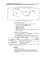
(d) When a circle center is designated to continuously designate the circular
interpolation control by a continuous path designation in the near pass mode,
and the positioning address and starting point address of that arc are the
same address, the path will make one circle using the two data items. This is
because the 2nd data starting point address is shifted by the extra amount of
the movement amount occurring from the 1st data.
Path of positioning data No.1
Starting point address of positioning data No.1
Starting point address of
positioning data No.2
Path of positioning data No.2
Path makes two circles because
the starting point addresses for
positioning data No.1 and 2 are the same.
[Positioning address pass mode]
[Near pass mode]
Example
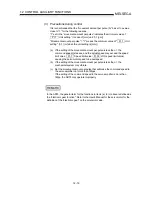
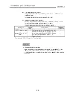
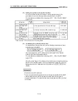
(3) Setting the near pass mode function
To use the "near path pass mode function", set the "near pass mode" in the
parameter shown in the following table, and write it to the AD75.
The set details are validated at the rising edge (OFF ON) of the PLC READY
signal (Y1D).
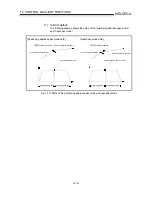
Setting item
Setting
value
Setting details
Factory-set initial value
Pr.44
Near pass mode
selection for path
control
1
Set "1: Near pass mode".
0: Positioning address pass mode
* Refer to section "5.2 List of parameters" for setting details.
Содержание A1SD75M1
Страница 2: ......
Страница 20: ...A 18 MEMO...
Страница 22: ...MEMO...
Страница 27: ...1 5 MELSEC A 1 PRODUCT OUTLINE MEMO...
Страница 42: ...1 20 MELSEC A 1 PRODUCT OUTLINE MEMO...
Страница 52: ...2 10 MELSEC A 2 SYSTEM CONFIGURATION MEMO...
Страница 111: ...5 21 MELSEC A 5 DATA USED FOR POSITIONING CONTROL MEMO...
Страница 115: ...5 25 MELSEC A 5 DATA USED FOR POSITIONING CONTROL MEMO...
Страница 123: ...5 33 MELSEC A 5 DATA USED FOR POSITIONING CONTROL MEMO...
Страница 127: ...5 37 MELSEC A 5 DATA USED FOR POSITIONING CONTROL MEMO...
Страница 167: ...5 77 MELSEC A 5 DATA USED FOR POSITIONING CONTROL MEMO...
Страница 193: ...5 103 MELSEC A 5 DATA USED FOR POSITIONING CONTROL MEMO...
Страница 276: ...5 186 MELSEC A 5 DATA USED FOR POSITIONING CONTROL MEMO...
Страница 332: ...7 18 MELSEC A 7 MEMORY CONFIGURATION AND DATA PROCESS MEMO...
Страница 334: ...MEMO...
Страница 422: ...9 64 MELSEC A 9 MAIN POSITIONING CONTROL MEMO...
Страница 446: ...10 24 MELSEC A 10 ADVANCED POSITIONING CONTROL MEMO...
Страница 472: ...11 26 MELSEC A 11 MANUAL CONTROL MEMO...
Страница 576: ...12 104 MELSEC A 12 CONTROL AUXILIARY FUNCTIONS MEMO...
Страница 673: ...Appendix 5 MELSEC A APPENDICES Axis address mm inch degree pulse Axis address mm inch degree pulse...
Страница 679: ...Appendix 11 MELSEC A APPENDICES Initial value Axis 1 Axis 2 Axis 3 Remarks 0 0 0 1 1 0 0 0 0 0 300 0 0 0...
Страница 683: ...Appendix 15 MELSEC A APPENDICES Initial value Axis 1 Axis 2 Axis 3 Remarks 0 0 1 0 0 50 80 0 0 980...
Страница 691: ...Appendix 23 MELSEC A APPENDICES Initial value Axis 1 Axis 2 Axis 3 Remarks 0 0 0 0 0 50 80 0 0 0 0 0 980 4000 0...
Страница 745: ......


