13 - 9
MELSEC-A
13 COMMON FUNCTIONS
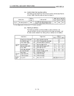
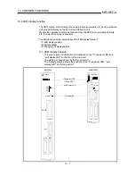
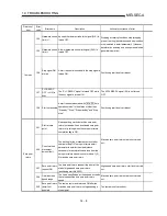
(b) "Operation monitor 2" display details
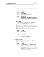
The axis operation status is displayed in the "operation monitor 2" mode.
The status display of each axis changes over every 0.5 seconds.
< Display >
< Details >
IDLE ............. Standing
by
STOP ........... Stopped
JOG.............. In JOG operation
MANP .......... In manual pulse generator operation
OPR ............. In zero point return
POSI ............ In position control
VELO ........... In speed control
V- P .............. In speed control of speed/position changeover control
V -P .............. In position control of speed/position changeover control
BUSY ........... Waiting for conditions, etc.
E
......... When an error occurs
Error No. display
When an error occurs in an axis, that error No. is displayed for 0.5
seconds before the display changes over to the next axis.
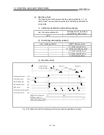
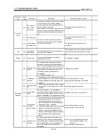
(c) "Input information n" display details
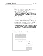
The status of each signal is displayed in the "input information n" mode.
The displayed signal is changed over in the following order every time the
"mode switch" is pressed.
The "axis display LED" is lit when the displayed signal is ON.
< Display >
< Details >
SVON........... Servo ON signal
ULMT ........... Upper limit signal
LLMT............ Lower limit signal
V-P ............... Speed/position changeover signal
DOG............. Near-point dog signal
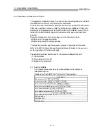
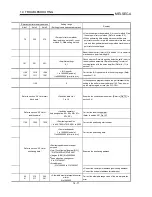
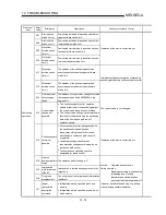
(d) Other display details
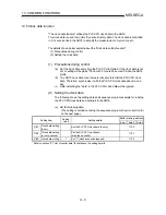
The following details are displayed in the 17-segment LED as error
messages, regardless of the mode.
< Display >
< Details >
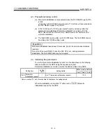
FALT ............ This error message may be displayed if any of the
parameter values saved in the flash ROM becomes
illegal. In this case, perform operation in the following
procedure. This error is due to a hardware fault if "FALT"
is still displayed after the operation has been performed in
the following procedure or if "FALT" is displayed in Step
3) of the following procedure.
Содержание A1SD75M1
Страница 2: ......
Страница 20: ...A 18 MEMO...
Страница 22: ...MEMO...
Страница 27: ...1 5 MELSEC A 1 PRODUCT OUTLINE MEMO...
Страница 42: ...1 20 MELSEC A 1 PRODUCT OUTLINE MEMO...
Страница 52: ...2 10 MELSEC A 2 SYSTEM CONFIGURATION MEMO...
Страница 111: ...5 21 MELSEC A 5 DATA USED FOR POSITIONING CONTROL MEMO...
Страница 115: ...5 25 MELSEC A 5 DATA USED FOR POSITIONING CONTROL MEMO...
Страница 123: ...5 33 MELSEC A 5 DATA USED FOR POSITIONING CONTROL MEMO...
Страница 127: ...5 37 MELSEC A 5 DATA USED FOR POSITIONING CONTROL MEMO...
Страница 167: ...5 77 MELSEC A 5 DATA USED FOR POSITIONING CONTROL MEMO...
Страница 193: ...5 103 MELSEC A 5 DATA USED FOR POSITIONING CONTROL MEMO...
Страница 276: ...5 186 MELSEC A 5 DATA USED FOR POSITIONING CONTROL MEMO...
Страница 332: ...7 18 MELSEC A 7 MEMORY CONFIGURATION AND DATA PROCESS MEMO...
Страница 334: ...MEMO...
Страница 422: ...9 64 MELSEC A 9 MAIN POSITIONING CONTROL MEMO...
Страница 446: ...10 24 MELSEC A 10 ADVANCED POSITIONING CONTROL MEMO...
Страница 472: ...11 26 MELSEC A 11 MANUAL CONTROL MEMO...
Страница 576: ...12 104 MELSEC A 12 CONTROL AUXILIARY FUNCTIONS MEMO...
Страница 673: ...Appendix 5 MELSEC A APPENDICES Axis address mm inch degree pulse Axis address mm inch degree pulse...
Страница 679: ...Appendix 11 MELSEC A APPENDICES Initial value Axis 1 Axis 2 Axis 3 Remarks 0 0 0 1 1 0 0 0 0 0 300 0 0 0...
Страница 683: ...Appendix 15 MELSEC A APPENDICES Initial value Axis 1 Axis 2 Axis 3 Remarks 0 0 1 0 0 50 80 0 0 980...
Страница 691: ...Appendix 23 MELSEC A APPENDICES Initial value Axis 1 Axis 2 Axis 3 Remarks 0 0 0 0 0 50 80 0 0 0 0 0 980 4000 0...
Страница 745: ......


