Appendix - 52
MELSEC-A
APPENDICES
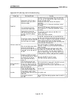
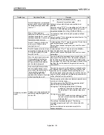
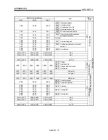
Trouble type
Questions/Trouble
Remedy
No.
Is it possible to count the pulses
when the B phase is set to "1", and
only A phase pulses are input?
Not possible.
(The AD75 counts 1, 0, 1, 0.)
36
Can a manual pulse generator
other than the Mitsubishi MR-
HDP01 be used?
Other manual pulse generators can be used if they
conform to section "3.5 Specifications of interfaces with
external devices."
37
Manual pulse
generator operation
Can one manual pulse generator
be operated connected to several
AD75 modules?
This is possible if the system conforms to the electrical
specifications.
38
Current value change
The BUSY signal is not canceled
by the current value change. How
can it be canceled?
The BUSY signal may remain if the scan time is long.
Use a complete signal to check whether the new value
has been executed.
39
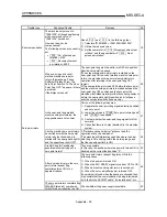
AD75 READY signal
The AD75 READY signal does not
turn OFF even when the PLC
READY signal [Y1D] is turned ON.
"A parameter error" has occurred.
Confirm the error No. in the error history, and correct the
parameter.
40
M code ON signal
Is there any problem with setting
an M code ON signal OFF request
in the next scan after the M code
ON signal ON?
The AD75 checks the M code ON signal OFF request
every "56.8ms", so there is a possibility that the M code
ON signal OFF may be delayed by a maximum of
"56.8ms" after the M code ON signal ON, even if an M
code ON signal OFF request is set.
41
Where is the current version of the
AD75 written?
The version is shown on the label on the front of the
module. (Refer to section "4.1.2 Names of each part".)
42
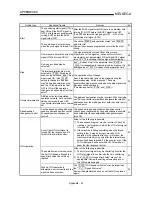
Is it possible that the delivered
module is a different version than
the version delivered 1 year ago?
That is possible.
43
Module
Error 537 (PLC READY OFF start)
occurred when the new module
was connected.
(The sequence program is the
same.)
The parameters in the module may differ.
Check if the AD75 READY signal [X0] turns OFF when
the PLC READY signal [Y1D] turns ON.
When the PLC READY signal is ON but the AD75 READY
signal is ON, the parameter error has occurred. Check the
error code and modify the parameter with the error.
44
The motor only rotates in one
direction.
The parameter settings on the AD75 side may not match
those on the servo side.
Check the parameter settings.
45
Motor
Can the current motor speed be
monitored?
The speed shown on the AD75 monitor is calculated from
the No. of pulses output from the module. Thus, the actual
motor speed cannot be monitored.
("
Md.31 Feedrate" monitors the commanded speed. It
does not show the actual speed.)
46
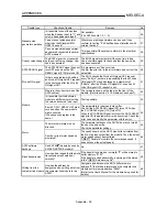
AD75 software
package
Can AD75M models be used by
SW0IVD-AD75P-E models?
No. 47
Block transmission
How can it be judged that the block
transmission was carried out
normally?
If the transfer is carried out normally, "0" will be stored in
buffer memory "5103".
If the transfer ended abnormally, a warning will be stored
in the "
Md.34 Axis warning No".
48
Writing from the
computer link module
How can the address be
designated when writing data from
the computer link module to the
AD75?
Designate an address in the AD75 buffer memory
address "0" that will be interpreted as the computer link
module buffer memory address "800H".
(Refer to the User's Manual for the module being used for
details.)
49
Содержание A1SD75M1
Страница 2: ......
Страница 20: ...A 18 MEMO...
Страница 22: ...MEMO...
Страница 27: ...1 5 MELSEC A 1 PRODUCT OUTLINE MEMO...
Страница 42: ...1 20 MELSEC A 1 PRODUCT OUTLINE MEMO...
Страница 52: ...2 10 MELSEC A 2 SYSTEM CONFIGURATION MEMO...
Страница 111: ...5 21 MELSEC A 5 DATA USED FOR POSITIONING CONTROL MEMO...
Страница 115: ...5 25 MELSEC A 5 DATA USED FOR POSITIONING CONTROL MEMO...
Страница 123: ...5 33 MELSEC A 5 DATA USED FOR POSITIONING CONTROL MEMO...
Страница 127: ...5 37 MELSEC A 5 DATA USED FOR POSITIONING CONTROL MEMO...
Страница 167: ...5 77 MELSEC A 5 DATA USED FOR POSITIONING CONTROL MEMO...
Страница 193: ...5 103 MELSEC A 5 DATA USED FOR POSITIONING CONTROL MEMO...
Страница 276: ...5 186 MELSEC A 5 DATA USED FOR POSITIONING CONTROL MEMO...
Страница 332: ...7 18 MELSEC A 7 MEMORY CONFIGURATION AND DATA PROCESS MEMO...
Страница 334: ...MEMO...
Страница 422: ...9 64 MELSEC A 9 MAIN POSITIONING CONTROL MEMO...
Страница 446: ...10 24 MELSEC A 10 ADVANCED POSITIONING CONTROL MEMO...
Страница 472: ...11 26 MELSEC A 11 MANUAL CONTROL MEMO...
Страница 576: ...12 104 MELSEC A 12 CONTROL AUXILIARY FUNCTIONS MEMO...
Страница 673: ...Appendix 5 MELSEC A APPENDICES Axis address mm inch degree pulse Axis address mm inch degree pulse...
Страница 679: ...Appendix 11 MELSEC A APPENDICES Initial value Axis 1 Axis 2 Axis 3 Remarks 0 0 0 1 1 0 0 0 0 0 300 0 0 0...
Страница 683: ...Appendix 15 MELSEC A APPENDICES Initial value Axis 1 Axis 2 Axis 3 Remarks 0 0 1 0 0 50 80 0 0 980...
Страница 691: ...Appendix 23 MELSEC A APPENDICES Initial value Axis 1 Axis 2 Axis 3 Remarks 0 0 0 0 0 50 80 0 0 0 0 0 980 4000 0...
Страница 745: ......

