12 - 69
MELSEC-A
12 CONTROL AUXILIARY FUNCTIONS
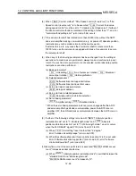
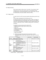
(b) When "Md.121 Absolute position restoration mode" is not switched
"Md.120 FeRAM access count" increases by "2".
(11) If the "Md.120 FeRAM access count" exceeds 9.9999 10
9
times at automatic
updating of the absolute position of the zero point, a warning "automatic
update count over" (warning code: 11) occurs.
(12) If write to the FeRAM is not completed normally at automatic updating of the
absolute position of the zero point, a warning "automatic update failure"
(warning code: 12) occurs.
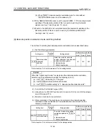
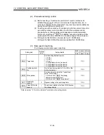
[4] Absolute position restoration mode switching method
The method of switching the absolute position restoration mode is described below.
(1) Set the following parameter.
Buffer memory address
Setting item
Setting
value
Setting details
Axis 1 Axis 2 Axis 3
Pr.59
Absolute position
restoration
selection
Select the mode for absolute
position restoration in an absolute
position detection system.
0: Standard mode
1: Infinite length mode
91 241 391
* Refer to section "5.2 List of parameters" for the setting details.
POINT
When the "infinite length mode" is selected as the absolute position restoration
selection, set the parameters to satisfy the following (a) to (c).
(a) Set "
Pr.1
Unit setting" to "2: degree".
(b) Set the software stroke limit function invalid.
(c) Set "
Pr.101
Amplifier setting" to "1: Absolute position detection valid".
(2) Turn ON the PLC READY signal (Y1D).
(3) Using the servo ON/OFF function (refer to section 12.4.5), turn ON the all axes
servo ON signal (Y15).
(4) Execute a machine zero point return.
(5) After completion of the machine zero point return, the absolute position
restoration mode is established. The established mode is stored into the
following monitor data.
Buffer memory address
Setting item
Monitor
value
Storage details
Axis 1 Axis 2 Axis 3
Md.121
Absolute position
restoration mode
The mode for absolute position
restoration selected in
Pr.59
is
stored.
0: Standard mode
1: Infinite length mode
879 979 1079
* Refer to section "5.6 List of monitor data" for the storage details.
Содержание A1SD75M1
Страница 2: ......
Страница 20: ...A 18 MEMO...
Страница 22: ...MEMO...
Страница 27: ...1 5 MELSEC A 1 PRODUCT OUTLINE MEMO...
Страница 42: ...1 20 MELSEC A 1 PRODUCT OUTLINE MEMO...
Страница 52: ...2 10 MELSEC A 2 SYSTEM CONFIGURATION MEMO...
Страница 111: ...5 21 MELSEC A 5 DATA USED FOR POSITIONING CONTROL MEMO...
Страница 115: ...5 25 MELSEC A 5 DATA USED FOR POSITIONING CONTROL MEMO...
Страница 123: ...5 33 MELSEC A 5 DATA USED FOR POSITIONING CONTROL MEMO...
Страница 127: ...5 37 MELSEC A 5 DATA USED FOR POSITIONING CONTROL MEMO...
Страница 167: ...5 77 MELSEC A 5 DATA USED FOR POSITIONING CONTROL MEMO...
Страница 193: ...5 103 MELSEC A 5 DATA USED FOR POSITIONING CONTROL MEMO...
Страница 276: ...5 186 MELSEC A 5 DATA USED FOR POSITIONING CONTROL MEMO...
Страница 332: ...7 18 MELSEC A 7 MEMORY CONFIGURATION AND DATA PROCESS MEMO...
Страница 334: ...MEMO...
Страница 422: ...9 64 MELSEC A 9 MAIN POSITIONING CONTROL MEMO...
Страница 446: ...10 24 MELSEC A 10 ADVANCED POSITIONING CONTROL MEMO...
Страница 472: ...11 26 MELSEC A 11 MANUAL CONTROL MEMO...
Страница 576: ...12 104 MELSEC A 12 CONTROL AUXILIARY FUNCTIONS MEMO...
Страница 673: ...Appendix 5 MELSEC A APPENDICES Axis address mm inch degree pulse Axis address mm inch degree pulse...
Страница 679: ...Appendix 11 MELSEC A APPENDICES Initial value Axis 1 Axis 2 Axis 3 Remarks 0 0 0 1 1 0 0 0 0 0 300 0 0 0...
Страница 683: ...Appendix 15 MELSEC A APPENDICES Initial value Axis 1 Axis 2 Axis 3 Remarks 0 0 1 0 0 50 80 0 0 980...
Страница 691: ...Appendix 23 MELSEC A APPENDICES Initial value Axis 1 Axis 2 Axis 3 Remarks 0 0 0 0 0 50 80 0 0 0 0 0 980 4000 0...
Страница 745: ......

