A - 6
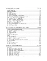
3. SPECIFICATIONS AND FUNCTIONS
3-1 to 3-18
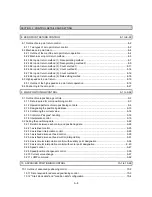
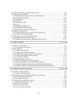
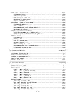
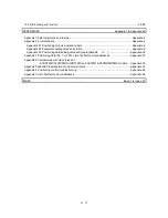
3.1 General specifications................................................................................................................................ 3-2
3.2 Performance specifications........................................................................................................................ 3-3
3.3 List of functions .......................................................................................................................................... 3-4
3.3.1 AD75 control functions ........................................................................................................................ 3-4
3.3.2 AD75 main functions ........................................................................................................................... 3-6
3.3.3 AD75 auxiliary functions and common functions ............................................................................... 3-8
3.3.4 Combination of AD75 main functions and auxiliary functions ......................................................... 3-10
3.4 Specifications of input/output signals with PLC CPU ............................................................................ 3-12
3.4.1 List of input/output signals with PLC CPU........................................................................................ 3-12
3.4.2 Details of input signals (AD75 PLC CPU) ................................................................................... 3-13
3.4.3 Details of output signals (PLC CPU AD75) ................................................................................. 3-14
3.5 Specifications of interfaces with external devices................................................................................... 3-15
3.5.1 Electrical specifications of input signals ........................................................................................... 3-15
3.5.2 Signal layout for external device connection connector................................................................... 3-16
3.5.3 List of input signal details ................................................................................................................. 3-17
3.5.4 Interface internal circuit .................................................................................................................... 3-18
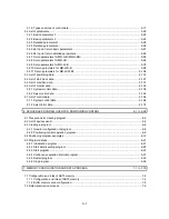
4. INSTALLATION, WIRING AND MAINTENANCE OF THE PRODUCT
4-1 to 4-20
4.1 Outline of installation, wiring and maintenance......................................................................................... 4-2
4.1.1 Installation, wiring and maintenance procedures............................................................................... 4-2
4.1.2 Names of each part............................................................................................................................. 4-3
4.1.3 Handling precautions .......................................................................................................................... 4-5
4.2 Installation .................................................................................................................................................. 4-7
4.2.1 Precautions for installation.................................................................................................................. 4-7
4.3 Wiring.......................................................................................................................................................... 4-8
4.3.1 Precautions for wiring.......................................................................................................................... 4-8
4.3.2 Wiring the external device connection connector pins..................................................................... 4-12
4.4 Confirming the installation and wiring...................................................................................................... 4-16
4.4.1 Items to confirm when installation and wiring are completed .......................................................... 4-16
4.4.2 Single module test............................................................................................................................. 4-17
4.5 Maintenance............................................................................................................................................. 4-20
4.5.1 Precautions for maintenance ............................................................................................................ 4-20
4.5.2 Disposal instructions ......................................................................................................................... 4-20
5. DATA USED FOR POSITIONING CONTROL
5-1 to 5-186
5.1 Types of data.............................................................................................................................................. 5-2
5.1.1 Parameters and data required for control........................................................................................... 5-2
5.1.2 Setting items for positioning parameters ............................................................................................ 5-4
5.1.3 Setting items for zero point return parameters................................................................................... 5-6
5.1.4 Setting items for servo parameters..................................................................................................... 5-7
5.1.5 Setting items for positioning data........................................................................................................ 5-9
5.1.6 Setting items for start block data ...................................................................................................... 5-11
5.1.7 Setting items for condition data ........................................................................................................ 5-12
5.1.8 Types and roles of monitor data ....................................................................................................... 5-13
Содержание A1SD75M1
Страница 2: ......
Страница 20: ...A 18 MEMO...
Страница 22: ...MEMO...
Страница 27: ...1 5 MELSEC A 1 PRODUCT OUTLINE MEMO...
Страница 42: ...1 20 MELSEC A 1 PRODUCT OUTLINE MEMO...
Страница 52: ...2 10 MELSEC A 2 SYSTEM CONFIGURATION MEMO...
Страница 111: ...5 21 MELSEC A 5 DATA USED FOR POSITIONING CONTROL MEMO...
Страница 115: ...5 25 MELSEC A 5 DATA USED FOR POSITIONING CONTROL MEMO...
Страница 123: ...5 33 MELSEC A 5 DATA USED FOR POSITIONING CONTROL MEMO...
Страница 127: ...5 37 MELSEC A 5 DATA USED FOR POSITIONING CONTROL MEMO...
Страница 167: ...5 77 MELSEC A 5 DATA USED FOR POSITIONING CONTROL MEMO...
Страница 193: ...5 103 MELSEC A 5 DATA USED FOR POSITIONING CONTROL MEMO...
Страница 276: ...5 186 MELSEC A 5 DATA USED FOR POSITIONING CONTROL MEMO...
Страница 332: ...7 18 MELSEC A 7 MEMORY CONFIGURATION AND DATA PROCESS MEMO...
Страница 334: ...MEMO...
Страница 422: ...9 64 MELSEC A 9 MAIN POSITIONING CONTROL MEMO...
Страница 446: ...10 24 MELSEC A 10 ADVANCED POSITIONING CONTROL MEMO...
Страница 472: ...11 26 MELSEC A 11 MANUAL CONTROL MEMO...
Страница 576: ...12 104 MELSEC A 12 CONTROL AUXILIARY FUNCTIONS MEMO...
Страница 673: ...Appendix 5 MELSEC A APPENDICES Axis address mm inch degree pulse Axis address mm inch degree pulse...
Страница 679: ...Appendix 11 MELSEC A APPENDICES Initial value Axis 1 Axis 2 Axis 3 Remarks 0 0 0 1 1 0 0 0 0 0 300 0 0 0...
Страница 683: ...Appendix 15 MELSEC A APPENDICES Initial value Axis 1 Axis 2 Axis 3 Remarks 0 0 1 0 0 50 80 0 0 980...
Страница 691: ...Appendix 23 MELSEC A APPENDICES Initial value Axis 1 Axis 2 Axis 3 Remarks 0 0 0 0 0 50 80 0 0 0 0 0 980 4000 0...
Страница 745: ......

