1 - 12
MELSEC-A
1 PRODUCT OUTLINE
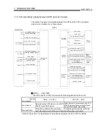
1.1.5 Communicating signals between AD75 and each module
The outline of signal communication between the AD75 and PLC CPU, peripheral
device, servo amplifier, etc. is shown below.
PLC READY signal
AD75 READY signal
All axes servo ON signal
Positioning start signal
Positioning complete signal
BUSY signal
Axis stop signal
Start complete signal
M code ON signal
Error detection signal
Servo
amplifier
Manual pulse generator A-phase
Manual pulse generator B-phase
Speed/position changeover signal
Manual
pulse
generator
External
signal
Positioning data write/read
Positioning start information write/read
Operation monitor
Parameter write/read
JOG operation (test)
Positioning operation (test)
Zero point return operation (test)
Peripheral
device
AD75
Data write/read
Y1D
XD,XE,XF
Y10,Y11,Y12
X7, X8, X9
X0
Peripheral
device
interface
Interface with
PLC CPU
Y15
X4, X5, X6
X1, X2, X3
Y13, Y14, Y1C
XA,XB,XC
PLC CPU
Stop signal
External start signal
Reverse run JOG start signal
Y16, Y18, Y1A
Y17, Y19, Y1B
Upper/lower limit signal
External
signal
Near-point dog signal
Servo status
External
interface
Servo ON
Monitor data
Position/speed command
Zero point
SSCNET
interface
Foward run JOG start signal
AD75
PLC CPU
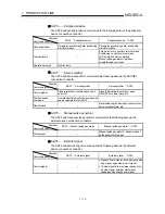
The AD75 and PLC CPU communicate the following data via the base unit.
Direction
Communication
AD75
PLC CPU
PLC CPU
AD75
Control signal *
Signal indicating AD75 state, such as AD75
READY signal, BUSY signal.
Signal related to commands such as PLC
READY signal, all axes servo ON signal,
various start signals, stop signals
Data (read/write)
Parameter, positioning data, positioning
start information, monitor data, control data
Parameter, positioning data, positioning
start information, control data
* Refer to the section "3.4 Specifications of input/output signals with PLC CPU" for details.
Содержание A1SD75M1
Страница 2: ......
Страница 20: ...A 18 MEMO...
Страница 22: ...MEMO...
Страница 27: ...1 5 MELSEC A 1 PRODUCT OUTLINE MEMO...
Страница 42: ...1 20 MELSEC A 1 PRODUCT OUTLINE MEMO...
Страница 52: ...2 10 MELSEC A 2 SYSTEM CONFIGURATION MEMO...
Страница 111: ...5 21 MELSEC A 5 DATA USED FOR POSITIONING CONTROL MEMO...
Страница 115: ...5 25 MELSEC A 5 DATA USED FOR POSITIONING CONTROL MEMO...
Страница 123: ...5 33 MELSEC A 5 DATA USED FOR POSITIONING CONTROL MEMO...
Страница 127: ...5 37 MELSEC A 5 DATA USED FOR POSITIONING CONTROL MEMO...
Страница 167: ...5 77 MELSEC A 5 DATA USED FOR POSITIONING CONTROL MEMO...
Страница 193: ...5 103 MELSEC A 5 DATA USED FOR POSITIONING CONTROL MEMO...
Страница 276: ...5 186 MELSEC A 5 DATA USED FOR POSITIONING CONTROL MEMO...
Страница 332: ...7 18 MELSEC A 7 MEMORY CONFIGURATION AND DATA PROCESS MEMO...
Страница 334: ...MEMO...
Страница 422: ...9 64 MELSEC A 9 MAIN POSITIONING CONTROL MEMO...
Страница 446: ...10 24 MELSEC A 10 ADVANCED POSITIONING CONTROL MEMO...
Страница 472: ...11 26 MELSEC A 11 MANUAL CONTROL MEMO...
Страница 576: ...12 104 MELSEC A 12 CONTROL AUXILIARY FUNCTIONS MEMO...
Страница 673: ...Appendix 5 MELSEC A APPENDICES Axis address mm inch degree pulse Axis address mm inch degree pulse...
Страница 679: ...Appendix 11 MELSEC A APPENDICES Initial value Axis 1 Axis 2 Axis 3 Remarks 0 0 0 1 1 0 0 0 0 0 300 0 0 0...
Страница 683: ...Appendix 15 MELSEC A APPENDICES Initial value Axis 1 Axis 2 Axis 3 Remarks 0 0 1 0 0 50 80 0 0 980...
Страница 691: ...Appendix 23 MELSEC A APPENDICES Initial value Axis 1 Axis 2 Axis 3 Remarks 0 0 0 0 0 50 80 0 0 0 0 0 980 4000 0...
Страница 745: ......


