5 - 6
MELSEC-A
5 DATA USED FOR POSITIONING CONTROL
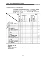
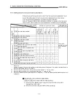
5.1.3 Setting items for zero point return parameters
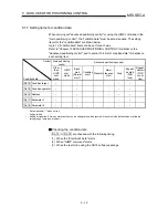
When carrying out "zero point return control", the "zero point return parameters" must
be set. The setting items for the "zero point return parameters" are shown below.
The "zero point return parameters" are set commonly for each axis.
Refer to "Chapter 8 ZERO POINT RETURN CONTROL" for details on the "zero point
return control", and to section "5.2 List of parameters" for details on each setting item.
Zero point return control
Zero point return parameters
Machine zero point return control
High-speed zero
point return control
Pr.45 Zero point return method
N
ear-point
dog method
N
ear-point
dog method
2
)
C
ount
method 1)
C
ount
method 2)
C
ount
method 3)
Data setting
method
Pr.46 Zero point return direction
–
Pr.47 Zero point address
Pr.48 Zero point return speed
–
Pr.49 Creep speed
–
Zero point return basic
parameters
Pr.50 Zero point return retry
R
R
R
R
R
–
Pr.52
Setting for the movement amount after
near-point dog ON
– –
–
Pr.53
Zero point return acceleration time
selection
–
Pr.54
Zero point return deceleration time
selection
–
Pr.55 Zero point shift amount
S
S
S
S
S
–
Pr.56 Zero point return torque limit value
–
–
–
–
–
–
Pr.57
Speed designation during zero point
shift
S S S S S –
Pr.58
Dwell time during zero point return
retry
R R R R R –
Zero point return detailed parameters
Pr.59 Absolute
position
restoration
selection
A A A A A A
Value set for
machine zero point
return control are
used.
: Always set
– : Setting not required (This is an irrelevant item, so the setting value will be ignored. If the value is the default value or
within the setting range, there is no problem.)
R : Set when using the section "12.2.1 Zero point return retry function". ("–" when not set.)
S : Set when using the section "12.2.2 Zero point shift function". ("–" when not set.)
A : Set when an absolute position detection system is configured. ("–" when an absolute position detection system is not
configured.)
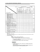
Checking the zero point return parameters.
Pr.45 to Pr.59 are checked with the following timing.
(1) When the "PLC READY signal" output from the PLC CPU to the AD75
changes from OFF to ON
(2) When the test mode using the AD75 software package
Содержание A1SD75M1
Страница 2: ......
Страница 20: ...A 18 MEMO...
Страница 22: ...MEMO...
Страница 27: ...1 5 MELSEC A 1 PRODUCT OUTLINE MEMO...
Страница 42: ...1 20 MELSEC A 1 PRODUCT OUTLINE MEMO...
Страница 52: ...2 10 MELSEC A 2 SYSTEM CONFIGURATION MEMO...
Страница 111: ...5 21 MELSEC A 5 DATA USED FOR POSITIONING CONTROL MEMO...
Страница 115: ...5 25 MELSEC A 5 DATA USED FOR POSITIONING CONTROL MEMO...
Страница 123: ...5 33 MELSEC A 5 DATA USED FOR POSITIONING CONTROL MEMO...
Страница 127: ...5 37 MELSEC A 5 DATA USED FOR POSITIONING CONTROL MEMO...
Страница 167: ...5 77 MELSEC A 5 DATA USED FOR POSITIONING CONTROL MEMO...
Страница 193: ...5 103 MELSEC A 5 DATA USED FOR POSITIONING CONTROL MEMO...
Страница 276: ...5 186 MELSEC A 5 DATA USED FOR POSITIONING CONTROL MEMO...
Страница 332: ...7 18 MELSEC A 7 MEMORY CONFIGURATION AND DATA PROCESS MEMO...
Страница 334: ...MEMO...
Страница 422: ...9 64 MELSEC A 9 MAIN POSITIONING CONTROL MEMO...
Страница 446: ...10 24 MELSEC A 10 ADVANCED POSITIONING CONTROL MEMO...
Страница 472: ...11 26 MELSEC A 11 MANUAL CONTROL MEMO...
Страница 576: ...12 104 MELSEC A 12 CONTROL AUXILIARY FUNCTIONS MEMO...
Страница 673: ...Appendix 5 MELSEC A APPENDICES Axis address mm inch degree pulse Axis address mm inch degree pulse...
Страница 679: ...Appendix 11 MELSEC A APPENDICES Initial value Axis 1 Axis 2 Axis 3 Remarks 0 0 0 1 1 0 0 0 0 0 300 0 0 0...
Страница 683: ...Appendix 15 MELSEC A APPENDICES Initial value Axis 1 Axis 2 Axis 3 Remarks 0 0 1 0 0 50 80 0 0 980...
Страница 691: ...Appendix 23 MELSEC A APPENDICES Initial value Axis 1 Axis 2 Axis 3 Remarks 0 0 0 0 0 50 80 0 0 0 0 0 980 4000 0...
Страница 745: ......

