12 - 61
MELSEC-A
12 CONTROL AUXILIARY FUNCTIONS
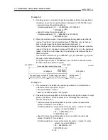
Condition 1. Number of output pulses
(a) It indicates the number of pulses that can be output to the servo amplifier
when positioning is started from the zero point in the absolute position
detection system. In the absolute position detection system, pulses within
the range of the following expression can be output.
[ 32768 (number of feedback pulses)] [number of output pulses] [32768 (number of feedback pulses) 1]
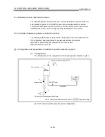
(b) The direction in which the address increases from the zero point is positive,
and the direction in which the address decreases from the zero point is
negative.
Zero point
0
Negative pulse output
Positive pulse output
-214748364.8
214748364.7
Unit :
µ
m
(c) The number of output pulses changes depending on the number of
feedback pulses as indicated below.
•
When the number of feedback pulses is 8192 (pulse):
268435456 (pulse) to 268435455 (pulse)
•
When the number of feedback pulses is 16384 (pulse):
536870912 (pulse) to 536870911 (pulse)
Condition 2. Positioning address
(a) The positioning addresses that can be specified for the AD75 are as
indicated below.
•
When the unit is mm: 214748364.8 (µm) to 214748364.7 (µm)
•
When the unit is inch: 21474.83648 (inch) to 21474.83647 (inch)
•
When the unit is pulse: 2147483648 (pulse) to 2147483647 (pulse)
•
When the unit is degree:0° to 359.99999°
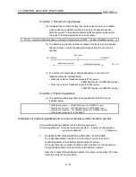
[Calculation of positioning address and concept of absolute position detection system]
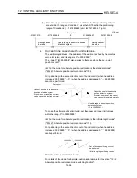
Calculate the positioning address with the following expression.
(Positioning address) = (movement amount per pulse) (number of output pulses)
+ (zero point address) ......................................... Expression 1
1.
Concept in the case where the unit is mm, inch or pulse
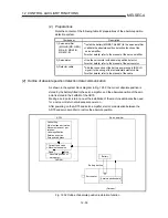
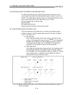
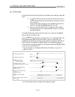
The range that satisfies Condition 1 and Condition 2 can be used as the
positioning address of the absolute position detection system.
The range that does not satisfy Condition 1 and Condition 2 cannot be used as
the positioning address of the absolute position detection system.
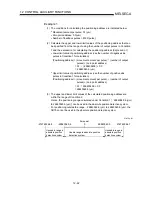
Since the concept of the positioning address is the same, an example of the case
where the unit is mm is given below.
Содержание A1SD75M1
Страница 2: ......
Страница 20: ...A 18 MEMO...
Страница 22: ...MEMO...
Страница 27: ...1 5 MELSEC A 1 PRODUCT OUTLINE MEMO...
Страница 42: ...1 20 MELSEC A 1 PRODUCT OUTLINE MEMO...
Страница 52: ...2 10 MELSEC A 2 SYSTEM CONFIGURATION MEMO...
Страница 111: ...5 21 MELSEC A 5 DATA USED FOR POSITIONING CONTROL MEMO...
Страница 115: ...5 25 MELSEC A 5 DATA USED FOR POSITIONING CONTROL MEMO...
Страница 123: ...5 33 MELSEC A 5 DATA USED FOR POSITIONING CONTROL MEMO...
Страница 127: ...5 37 MELSEC A 5 DATA USED FOR POSITIONING CONTROL MEMO...
Страница 167: ...5 77 MELSEC A 5 DATA USED FOR POSITIONING CONTROL MEMO...
Страница 193: ...5 103 MELSEC A 5 DATA USED FOR POSITIONING CONTROL MEMO...
Страница 276: ...5 186 MELSEC A 5 DATA USED FOR POSITIONING CONTROL MEMO...
Страница 332: ...7 18 MELSEC A 7 MEMORY CONFIGURATION AND DATA PROCESS MEMO...
Страница 334: ...MEMO...
Страница 422: ...9 64 MELSEC A 9 MAIN POSITIONING CONTROL MEMO...
Страница 446: ...10 24 MELSEC A 10 ADVANCED POSITIONING CONTROL MEMO...
Страница 472: ...11 26 MELSEC A 11 MANUAL CONTROL MEMO...
Страница 576: ...12 104 MELSEC A 12 CONTROL AUXILIARY FUNCTIONS MEMO...
Страница 673: ...Appendix 5 MELSEC A APPENDICES Axis address mm inch degree pulse Axis address mm inch degree pulse...
Страница 679: ...Appendix 11 MELSEC A APPENDICES Initial value Axis 1 Axis 2 Axis 3 Remarks 0 0 0 1 1 0 0 0 0 0 300 0 0 0...
Страница 683: ...Appendix 15 MELSEC A APPENDICES Initial value Axis 1 Axis 2 Axis 3 Remarks 0 0 1 0 0 50 80 0 0 980...
Страница 691: ...Appendix 23 MELSEC A APPENDICES Initial value Axis 1 Axis 2 Axis 3 Remarks 0 0 0 0 0 50 80 0 0 0 0 0 980 4000 0...
Страница 745: ......


