1 - 18
MELSEC-A
1 PRODUCT OUTLINE
1.2.3 Outline of stopping
Each control is stopped in the following cases.
(1) When each control is completed normally.
(2) When Servo alarm (
Md.116
Servo status: b13) turns ON
(3) When the PLC READY signal is turned OFF (When "parameter error" or "watch
dog timer error" occurs in PLC CPU.)
(4) When an error occurs.
(5) When control is intentionally stopped (Stop signal from PLC CPU turned ON, stop
from peripheral device, etc.)
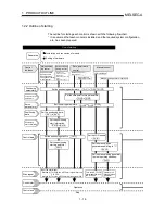
The outline for the stopping process in these cases is shown below. (Excluding (1) for
normal stopping.)
Stop process
Zero point return
control
Manual control
Stop cause
Stop
axis
Axis
operation
status after
stopping
(
Md.35 )
Machine
zero point
return
control
High-
speed
zero
point
return
control
Main
positioning
control
Advanced
positioning
control
JOG
opera-
tion
Manual
pulse
generator
operation
Forced stop
Servo alarm
turns ON and
Servo ON turns
OFF
(
Md.116
Servo
status: b1, b13)
Each
axis
During
error
Immediate
stop
Immediate
stop
Fatal stop
(Stop group 1)
Hardware stroke
limit upper/lower
limit error
occurrence
Each
axis
During
error
Deceleration stop/sudden stop
(Select with
Pr.38 )
Deceleration
stop
Software stroke
limit upper/lower
limit error
occurrence
Each
axis
PLC READY
signal OFF
Emergency
stop
(Stop group 2)
"Stop" input from
peripheral device
All
axes
During
error
Deceleration stop/sudden stop
(Select with
Pr.39 )
Deceleration
stop
Axis error
detection (Error
other than stop
group 1 or 2)
Relatively safe
stop
(Stop group 3)
Error in test
mode
Each
axis
During
error
"Stop signal" ON
from external
source
Intentional stop
(Stop group 3) "Axis stop signal"
ON from PLC
CPU
Each
axis
When
stopped
Deceleration stop/sudden stop
(Select with
Pr.40 )
Deceleration
stop
Содержание A1SD75M1
Страница 2: ......
Страница 20: ...A 18 MEMO...
Страница 22: ...MEMO...
Страница 27: ...1 5 MELSEC A 1 PRODUCT OUTLINE MEMO...
Страница 42: ...1 20 MELSEC A 1 PRODUCT OUTLINE MEMO...
Страница 52: ...2 10 MELSEC A 2 SYSTEM CONFIGURATION MEMO...
Страница 111: ...5 21 MELSEC A 5 DATA USED FOR POSITIONING CONTROL MEMO...
Страница 115: ...5 25 MELSEC A 5 DATA USED FOR POSITIONING CONTROL MEMO...
Страница 123: ...5 33 MELSEC A 5 DATA USED FOR POSITIONING CONTROL MEMO...
Страница 127: ...5 37 MELSEC A 5 DATA USED FOR POSITIONING CONTROL MEMO...
Страница 167: ...5 77 MELSEC A 5 DATA USED FOR POSITIONING CONTROL MEMO...
Страница 193: ...5 103 MELSEC A 5 DATA USED FOR POSITIONING CONTROL MEMO...
Страница 276: ...5 186 MELSEC A 5 DATA USED FOR POSITIONING CONTROL MEMO...
Страница 332: ...7 18 MELSEC A 7 MEMORY CONFIGURATION AND DATA PROCESS MEMO...
Страница 334: ...MEMO...
Страница 422: ...9 64 MELSEC A 9 MAIN POSITIONING CONTROL MEMO...
Страница 446: ...10 24 MELSEC A 10 ADVANCED POSITIONING CONTROL MEMO...
Страница 472: ...11 26 MELSEC A 11 MANUAL CONTROL MEMO...
Страница 576: ...12 104 MELSEC A 12 CONTROL AUXILIARY FUNCTIONS MEMO...
Страница 673: ...Appendix 5 MELSEC A APPENDICES Axis address mm inch degree pulse Axis address mm inch degree pulse...
Страница 679: ...Appendix 11 MELSEC A APPENDICES Initial value Axis 1 Axis 2 Axis 3 Remarks 0 0 0 1 1 0 0 0 0 0 300 0 0 0...
Страница 683: ...Appendix 15 MELSEC A APPENDICES Initial value Axis 1 Axis 2 Axis 3 Remarks 0 0 1 0 0 50 80 0 0 980...
Страница 691: ...Appendix 23 MELSEC A APPENDICES Initial value Axis 1 Axis 2 Axis 3 Remarks 0 0 0 0 0 50 80 0 0 0 0 0 980 4000 0...
Страница 745: ......


