11 - 21
MELSEC-A
11 MANUAL CONTROL
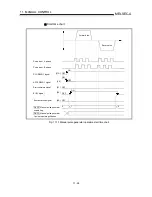
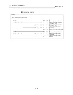
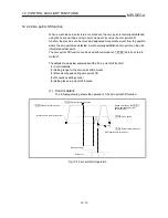
11.3.2 Manual pulse generator operation execution procedure
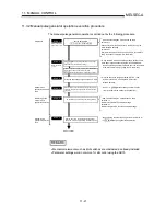
The manual pulse generator operation is carried out by the following procedure.
* Write the sequence program created in STEP 1 and
STEP 2 to the PLC CPU using the GPP function
software package.
* Using the GPP function software package, set the control
data and create a sequence program to enable/disable
the manual pulse generator operation. (Set the control data
in the AD75 buffer memory using the TO command.)
* One of the following two methods can be used.
<Method 1>
Directly set (write) the parameters in the AD75 using the
AD75 software package.
<Method 2>
Set (write) the parameters from the PLC CPU to the AD75
using the sequence program (TO command).
STEP 1
Manual pulse
generator operation
start
End of control
STEP 2
STEP 3
STEP 4
STEP 5
Issue a command to enable the manual pulse generator
operation, and input the signals from the manual pulse
generator.
End the input from the manual pulse generator,
and issue a command to disable the manual pulse
Manual pulse
generator operation
stop
STEP 6
Monitor the manual pulse generator operation.
Preparation
Refer to Chapter 5
and section 11.3.3.
Refer to section
11.3.4.
Write the sequence program to the PLC CPU.
* One of the following two methods can be used.
<Method 1>
Monitor using the AD75 software package.
<Method 2>
Monitor using the GPP function software package.
Monitoring of the
manual pulse
generator operation
Set " Cd. 23 Manual pulse generator 1 pulse input
magnification". (control data setting)
Create a sequence program in which the enable/disable is
(" Cd. 22 Manual pulse generator enable flag" setting.)
set for the manual pulse generator operation.
* Stop operating the manual pulse generator, and write "0"
in " Cd. 22 Manual pulse generator enable flag".
* Write "1" in " Cd.22 Manual pulse generator enable
flag", and operate the manual pulse generator.
Set the parameters
to
)
Pr.1
Pr.23
Pr.100
Pr.109
,
to
REMARK
•
Mechanical elements such as limit switches are considered as already installed.
•
Parameter settings work in common for all control using the AD75.
Содержание A1SD75M1
Страница 2: ......
Страница 20: ...A 18 MEMO...
Страница 22: ...MEMO...
Страница 27: ...1 5 MELSEC A 1 PRODUCT OUTLINE MEMO...
Страница 42: ...1 20 MELSEC A 1 PRODUCT OUTLINE MEMO...
Страница 52: ...2 10 MELSEC A 2 SYSTEM CONFIGURATION MEMO...
Страница 111: ...5 21 MELSEC A 5 DATA USED FOR POSITIONING CONTROL MEMO...
Страница 115: ...5 25 MELSEC A 5 DATA USED FOR POSITIONING CONTROL MEMO...
Страница 123: ...5 33 MELSEC A 5 DATA USED FOR POSITIONING CONTROL MEMO...
Страница 127: ...5 37 MELSEC A 5 DATA USED FOR POSITIONING CONTROL MEMO...
Страница 167: ...5 77 MELSEC A 5 DATA USED FOR POSITIONING CONTROL MEMO...
Страница 193: ...5 103 MELSEC A 5 DATA USED FOR POSITIONING CONTROL MEMO...
Страница 276: ...5 186 MELSEC A 5 DATA USED FOR POSITIONING CONTROL MEMO...
Страница 332: ...7 18 MELSEC A 7 MEMORY CONFIGURATION AND DATA PROCESS MEMO...
Страница 334: ...MEMO...
Страница 422: ...9 64 MELSEC A 9 MAIN POSITIONING CONTROL MEMO...
Страница 446: ...10 24 MELSEC A 10 ADVANCED POSITIONING CONTROL MEMO...
Страница 472: ...11 26 MELSEC A 11 MANUAL CONTROL MEMO...
Страница 576: ...12 104 MELSEC A 12 CONTROL AUXILIARY FUNCTIONS MEMO...
Страница 673: ...Appendix 5 MELSEC A APPENDICES Axis address mm inch degree pulse Axis address mm inch degree pulse...
Страница 679: ...Appendix 11 MELSEC A APPENDICES Initial value Axis 1 Axis 2 Axis 3 Remarks 0 0 0 1 1 0 0 0 0 0 300 0 0 0...
Страница 683: ...Appendix 15 MELSEC A APPENDICES Initial value Axis 1 Axis 2 Axis 3 Remarks 0 0 1 0 0 50 80 0 0 980...
Страница 691: ...Appendix 23 MELSEC A APPENDICES Initial value Axis 1 Axis 2 Axis 3 Remarks 0 0 0 0 0 50 80 0 0 0 0 0 980 4000 0...
Страница 745: ......


