A - 2
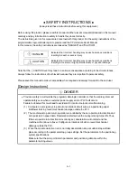
[Design Instructions]
!
CAUTION
Do not bundle or adjacently lay the control wire or communication cable with the main circuit or
power wire.
Separate these by 100mm or more.
Failure to observe this could lead to malfunctioning caused by noise.
[Mounting Instructions]
!
CAUTION
Use the PLC within the general specifications environment given in this manual.
Using the PLC outside the general specification range environment could lead to electric
shocks, fires, malfunctioning, product damage or deterioration.
Always securely insert the module latches at the bottom of the module into the fixing holes on
the base unit. (Always screw the AnS Series module onto the base unit with the specified
torque.)
Improper mounting of the module could lead to malfunctioning, faults or dropping.
Securely connect the external device connection connector, SSCNET connection connector
and peripheral device connection connector into the module connector until a click is heard.
Improper connection could lead to a connection fault, and to incorrect inputs and outputs.
When not connecting the external device, always install a cover on the connector section.
Failure to observe this could lead to malfunctioning.
[Wiring Instructions]
!
DANGER
Always confirm the terminal layout before connecting the wires to the module.
Make sure that foreign matter such as cutting chips and wire scraps does not enter the module.
Failure to observe this could lead to fires, faults or malfunctioning.
[Startup/Maintenance Instructions]
!
DANGER
Switch off all phases of the externally supplied power used in the system before cleaning or
tightening the screws.
Failure to turn all phases OFF could lead to electric shocks.
Содержание A1SD75M1
Страница 2: ......
Страница 20: ...A 18 MEMO...
Страница 22: ...MEMO...
Страница 27: ...1 5 MELSEC A 1 PRODUCT OUTLINE MEMO...
Страница 42: ...1 20 MELSEC A 1 PRODUCT OUTLINE MEMO...
Страница 52: ...2 10 MELSEC A 2 SYSTEM CONFIGURATION MEMO...
Страница 111: ...5 21 MELSEC A 5 DATA USED FOR POSITIONING CONTROL MEMO...
Страница 115: ...5 25 MELSEC A 5 DATA USED FOR POSITIONING CONTROL MEMO...
Страница 123: ...5 33 MELSEC A 5 DATA USED FOR POSITIONING CONTROL MEMO...
Страница 127: ...5 37 MELSEC A 5 DATA USED FOR POSITIONING CONTROL MEMO...
Страница 167: ...5 77 MELSEC A 5 DATA USED FOR POSITIONING CONTROL MEMO...
Страница 193: ...5 103 MELSEC A 5 DATA USED FOR POSITIONING CONTROL MEMO...
Страница 276: ...5 186 MELSEC A 5 DATA USED FOR POSITIONING CONTROL MEMO...
Страница 332: ...7 18 MELSEC A 7 MEMORY CONFIGURATION AND DATA PROCESS MEMO...
Страница 334: ...MEMO...
Страница 422: ...9 64 MELSEC A 9 MAIN POSITIONING CONTROL MEMO...
Страница 446: ...10 24 MELSEC A 10 ADVANCED POSITIONING CONTROL MEMO...
Страница 472: ...11 26 MELSEC A 11 MANUAL CONTROL MEMO...
Страница 576: ...12 104 MELSEC A 12 CONTROL AUXILIARY FUNCTIONS MEMO...
Страница 673: ...Appendix 5 MELSEC A APPENDICES Axis address mm inch degree pulse Axis address mm inch degree pulse...
Страница 679: ...Appendix 11 MELSEC A APPENDICES Initial value Axis 1 Axis 2 Axis 3 Remarks 0 0 0 1 1 0 0 0 0 0 300 0 0 0...
Страница 683: ...Appendix 15 MELSEC A APPENDICES Initial value Axis 1 Axis 2 Axis 3 Remarks 0 0 1 0 0 50 80 0 0 980...
Страница 691: ...Appendix 23 MELSEC A APPENDICES Initial value Axis 1 Axis 2 Axis 3 Remarks 0 0 0 0 0 50 80 0 0 0 0 0 980 4000 0...
Страница 745: ......

