11 - 1
Chapter 11
MANUAL CONTROL
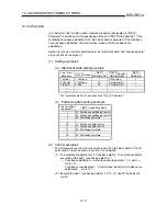
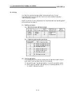
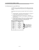
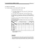
The details and usage of manual control are explained in this chapter.
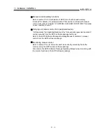
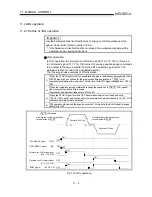
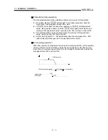
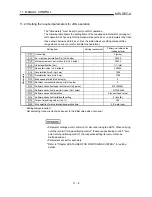
In manual control, pulse output commands are issued during a JOG operation executed
by the turning ON of the JOG START signal, or from a manual pulse generator
connected to the AD75.
Manual control using a sequence program from the PLC CPU is explained in this chapter.
Refer to the AD75 Software Package Operating Manual for an explanation of manual
control (JOG operation, manual pulse generator operation) using the AD75 software
package.
11.1 Outline of manual control ........................................................................................11- 2
11.1.1 Two manual control methods ....................................................................11- 2
11.2 JOG
operation..........................................................................................................11- 4
11.2.1 Outline of JOG operation ...........................................................................11- 4
11.2.2 JOG operation execution procedure .........................................................11- 7
11.2.3 Setting the required parameters for JOG operation .................................11- 8
11.2.4 Creating start programs for JOG operation..............................................11- 10
11.2.5 JOG operation example............................................................................11- 13
11.3 Manual pulse generator operation .........................................................................11- 17
11.3.1 Outline of manual pulse generator operation...........................................11- 17
11.3.2 Manual pulse generator operation execution procedure .........................11- 21
11.3.3 Setting the required parameters for manual pulse generator operation
...................................................................................................................11-
22
11.3.4 Creating a program to enable/disable the manual pulse generator
operation
...................................................................................................11-
23
11
Содержание A1SD75M1
Страница 2: ......
Страница 20: ...A 18 MEMO...
Страница 22: ...MEMO...
Страница 27: ...1 5 MELSEC A 1 PRODUCT OUTLINE MEMO...
Страница 42: ...1 20 MELSEC A 1 PRODUCT OUTLINE MEMO...
Страница 52: ...2 10 MELSEC A 2 SYSTEM CONFIGURATION MEMO...
Страница 111: ...5 21 MELSEC A 5 DATA USED FOR POSITIONING CONTROL MEMO...
Страница 115: ...5 25 MELSEC A 5 DATA USED FOR POSITIONING CONTROL MEMO...
Страница 123: ...5 33 MELSEC A 5 DATA USED FOR POSITIONING CONTROL MEMO...
Страница 127: ...5 37 MELSEC A 5 DATA USED FOR POSITIONING CONTROL MEMO...
Страница 167: ...5 77 MELSEC A 5 DATA USED FOR POSITIONING CONTROL MEMO...
Страница 193: ...5 103 MELSEC A 5 DATA USED FOR POSITIONING CONTROL MEMO...
Страница 276: ...5 186 MELSEC A 5 DATA USED FOR POSITIONING CONTROL MEMO...
Страница 332: ...7 18 MELSEC A 7 MEMORY CONFIGURATION AND DATA PROCESS MEMO...
Страница 334: ...MEMO...
Страница 422: ...9 64 MELSEC A 9 MAIN POSITIONING CONTROL MEMO...
Страница 446: ...10 24 MELSEC A 10 ADVANCED POSITIONING CONTROL MEMO...
Страница 472: ...11 26 MELSEC A 11 MANUAL CONTROL MEMO...
Страница 576: ...12 104 MELSEC A 12 CONTROL AUXILIARY FUNCTIONS MEMO...
Страница 673: ...Appendix 5 MELSEC A APPENDICES Axis address mm inch degree pulse Axis address mm inch degree pulse...
Страница 679: ...Appendix 11 MELSEC A APPENDICES Initial value Axis 1 Axis 2 Axis 3 Remarks 0 0 0 1 1 0 0 0 0 0 300 0 0 0...
Страница 683: ...Appendix 15 MELSEC A APPENDICES Initial value Axis 1 Axis 2 Axis 3 Remarks 0 0 1 0 0 50 80 0 0 980...
Страница 691: ...Appendix 23 MELSEC A APPENDICES Initial value Axis 1 Axis 2 Axis 3 Remarks 0 0 0 0 0 50 80 0 0 0 0 0 980 4000 0...
Страница 745: ......

