5 - 102
MELSEC-A
5 DATA USED FOR POSITIONING CONTROL
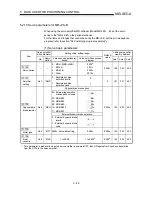
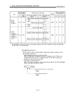
Servo amplifier
side parameter
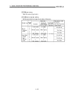
Setting value, setting range
Setting value buffer
memory address
Item
No.
Abbre-
viation
Value set with peripheral
device
Value set with sequence
program
Default
value
Axis 1 Axis 2 Axis 3
Pr.138
Encoder
output pulses
No.38 *ENR
–
0 to 65535
4000
138
288
438
Pr.149
Servo
parameter
transmission
setting
– –
–
0,
F003
H
0
149 299 449
* This parameter is made valid when the servo amplifier is powered OFF, then ON again after it has been transferred
from the AD75 to the servo amplifier.
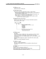
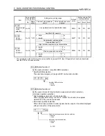
Pr.138
Encoder output pulses
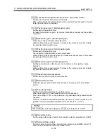
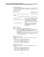
Set the encoder pulses (A phase, B phase) output by the servo amplifier. Set the
value 4 times smaller than the A phase and B phase pulses.
This parameter cannot be set on the peripheral device.
Set this parameter with a sequence program.
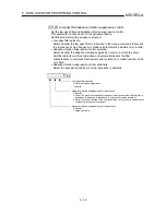
Use "
Pr.133
Option function 6" to select the output pulses setting or output
dividing frequency ratio setting.
The number of A phase and B phase pulses actually output is 1/4 times greater
than the preset number of pulses.
The maximum output frequency is 1.3Mpulse (after multiplication by 4). Use this
parameter within this range.
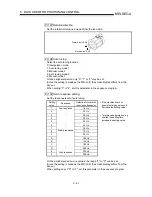
•
For output pulses setting
Set "
Pr.133
Option function 6" to "
0
H
" (initial value).
Set the number of pulses per servomotor revolution.
Output pulses = setting value [pulse/rev]
(Example) When the setting is 5600, the actually output A phase and B phase
pulses are as indicated below.
A phase and B phase output pulses =
5600
4
= 1400 [pulse]
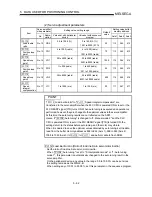
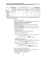
•
For dividing frequency ratio setting
Set "
Pr.133
Option function 6" to "
1
H
".
The number of pulses per servomotor revolution is divided by the setting value.
Output pulses =
Resoution per servomotor revolution
Setting value
[pulse/rev]
(Example) When the setting is 8, the actually output A phase and B phase
pulses are as indicated below.
A phase and B phase output pulses=
131072
8
1
4
= 4096 [pulse]
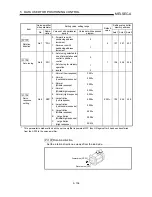
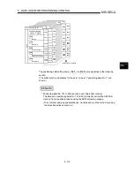
Pr.149
Servo parameter transmission setting
Set whether the encoder output pulse function and slight vibration suppression
function of the MR-J2S-B are valid or invalid.
This parameter cannot be set on the peripheral device.
Set this parameter with a sequence program.
0 : Invalid
F003
H
: Valid
Содержание A1SD75M1
Страница 2: ......
Страница 20: ...A 18 MEMO...
Страница 22: ...MEMO...
Страница 27: ...1 5 MELSEC A 1 PRODUCT OUTLINE MEMO...
Страница 42: ...1 20 MELSEC A 1 PRODUCT OUTLINE MEMO...
Страница 52: ...2 10 MELSEC A 2 SYSTEM CONFIGURATION MEMO...
Страница 111: ...5 21 MELSEC A 5 DATA USED FOR POSITIONING CONTROL MEMO...
Страница 115: ...5 25 MELSEC A 5 DATA USED FOR POSITIONING CONTROL MEMO...
Страница 123: ...5 33 MELSEC A 5 DATA USED FOR POSITIONING CONTROL MEMO...
Страница 127: ...5 37 MELSEC A 5 DATA USED FOR POSITIONING CONTROL MEMO...
Страница 167: ...5 77 MELSEC A 5 DATA USED FOR POSITIONING CONTROL MEMO...
Страница 193: ...5 103 MELSEC A 5 DATA USED FOR POSITIONING CONTROL MEMO...
Страница 276: ...5 186 MELSEC A 5 DATA USED FOR POSITIONING CONTROL MEMO...
Страница 332: ...7 18 MELSEC A 7 MEMORY CONFIGURATION AND DATA PROCESS MEMO...
Страница 334: ...MEMO...
Страница 422: ...9 64 MELSEC A 9 MAIN POSITIONING CONTROL MEMO...
Страница 446: ...10 24 MELSEC A 10 ADVANCED POSITIONING CONTROL MEMO...
Страница 472: ...11 26 MELSEC A 11 MANUAL CONTROL MEMO...
Страница 576: ...12 104 MELSEC A 12 CONTROL AUXILIARY FUNCTIONS MEMO...
Страница 673: ...Appendix 5 MELSEC A APPENDICES Axis address mm inch degree pulse Axis address mm inch degree pulse...
Страница 679: ...Appendix 11 MELSEC A APPENDICES Initial value Axis 1 Axis 2 Axis 3 Remarks 0 0 0 1 1 0 0 0 0 0 300 0 0 0...
Страница 683: ...Appendix 15 MELSEC A APPENDICES Initial value Axis 1 Axis 2 Axis 3 Remarks 0 0 1 0 0 50 80 0 0 980...
Страница 691: ...Appendix 23 MELSEC A APPENDICES Initial value Axis 1 Axis 2 Axis 3 Remarks 0 0 0 0 0 50 80 0 0 0 0 0 980 4000 0...
Страница 745: ......

