5 - 82
MELSEC-A
5 DATA USED FOR POSITIONING CONTROL
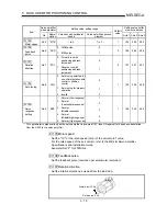
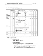
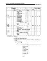
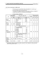
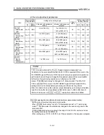
(2) Servo adjustment parameters
Servo amplifier
side parameter
Setting value, setting range
Setting value buffer
memory address
Item
No.
Abbre-
viation
Value set with peripheral
device
Value set with sequence
program
Default
value
Axis 1 Axis 2 Axis 3
Pr.112
Load inertia
ratio
No.12
GD2
0.0 to 100.0 (%)
0 to 1000 (0.1%)
30
112
262
412
Pr.113
Position loop
gain 1
No.13
PG1
4 to 1000 (rad/s)
4 to 1000 (rad/s)
70
113
263
413
Pr.114
Speed loop
gain 1
No.14
VG1
20 to 5000 (rad/s)
20 to 5000 (rad/s)
1200
114
264
414
Pr.115
Position loop
gain 2
No.15
PG2
1 to 500 (rad/s)
1 to 500 (rad/s)
25
115
265
415
Pr.116
Speed loop
gain 2
No.16
VG2
20 to 8000 (rad/s)
20 to 8000 (rad/s)
600
116
266
416
Pr.117
Speed
integral
compensation
No.17
VIC
1 to 1000 (ms)
1 to 1000 (ms)
20
117
267
417
0 : Not used
0
1 :
1125
1
2 :
563
2
3 :
375
3
4 :
282
4
5 :
225
5
6 :
188
6
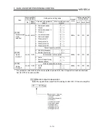
Pr.118
Notch filter
selection
No.18 NCH
7 :
161
7
0
118 268 418
Pr.119
Feed forward
gain
No.19
FFC
0 to 100 (%)
0 to 100 (%)
0
119
269
419
Pr.120
In-position
range
No.20
INP
0 to 50000 (pulse)
0 to 50000 (pulse)
100
120
270
420
Pr.121
Solenoid
brake output
No.21
MBR
0 to 1000 (ms)
0 to 1000 (ms)
100
121
271
421
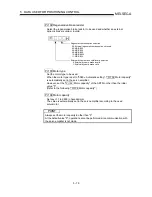
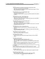
POINT
"
Pr.112
Load inertia ratio" to "
Pr.117
Speed integral compensation" are
transferred to the servo amplifier when the PLC CPU is powered ON or reset or the
PLC READY signal [Y1D] turns ON. When auto tuning is executed and operation is
performed, however, they are changed to the optimum values in the servo amplifier.
At this time, the auto tuning results are not reflected on the AD75.
Hence, if "
Pr.108
Auto tuning" is changed to "2: Invalid" and the PLC CPU is
powered ON or reset or the PLC READY signal [Y1D] is turned ON, the settings
return to the status before auto tuning, and the motor may vibrate.
When it is desired to save the optimum values obtained by auto tuning, set the data
read from the buffer memory addresses 858 to 863 (Axis 1), 958 to 963 (Axis 2),
1058 to 1063 (Axis 3) to
Pr.112
to
Pr.117
, and perform write to flash ROM.
Содержание A1SD75M1
Страница 2: ......
Страница 20: ...A 18 MEMO...
Страница 22: ...MEMO...
Страница 27: ...1 5 MELSEC A 1 PRODUCT OUTLINE MEMO...
Страница 42: ...1 20 MELSEC A 1 PRODUCT OUTLINE MEMO...
Страница 52: ...2 10 MELSEC A 2 SYSTEM CONFIGURATION MEMO...
Страница 111: ...5 21 MELSEC A 5 DATA USED FOR POSITIONING CONTROL MEMO...
Страница 115: ...5 25 MELSEC A 5 DATA USED FOR POSITIONING CONTROL MEMO...
Страница 123: ...5 33 MELSEC A 5 DATA USED FOR POSITIONING CONTROL MEMO...
Страница 127: ...5 37 MELSEC A 5 DATA USED FOR POSITIONING CONTROL MEMO...
Страница 167: ...5 77 MELSEC A 5 DATA USED FOR POSITIONING CONTROL MEMO...
Страница 193: ...5 103 MELSEC A 5 DATA USED FOR POSITIONING CONTROL MEMO...
Страница 276: ...5 186 MELSEC A 5 DATA USED FOR POSITIONING CONTROL MEMO...
Страница 332: ...7 18 MELSEC A 7 MEMORY CONFIGURATION AND DATA PROCESS MEMO...
Страница 334: ...MEMO...
Страница 422: ...9 64 MELSEC A 9 MAIN POSITIONING CONTROL MEMO...
Страница 446: ...10 24 MELSEC A 10 ADVANCED POSITIONING CONTROL MEMO...
Страница 472: ...11 26 MELSEC A 11 MANUAL CONTROL MEMO...
Страница 576: ...12 104 MELSEC A 12 CONTROL AUXILIARY FUNCTIONS MEMO...
Страница 673: ...Appendix 5 MELSEC A APPENDICES Axis address mm inch degree pulse Axis address mm inch degree pulse...
Страница 679: ...Appendix 11 MELSEC A APPENDICES Initial value Axis 1 Axis 2 Axis 3 Remarks 0 0 0 1 1 0 0 0 0 0 300 0 0 0...
Страница 683: ...Appendix 15 MELSEC A APPENDICES Initial value Axis 1 Axis 2 Axis 3 Remarks 0 0 1 0 0 50 80 0 0 980...
Страница 691: ...Appendix 23 MELSEC A APPENDICES Initial value Axis 1 Axis 2 Axis 3 Remarks 0 0 0 0 0 50 80 0 0 0 0 0 980 4000 0...
Страница 745: ......


