12 - 64
MELSEC-A
12 CONTROL AUXILIARY FUNCTIONS
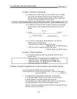
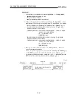
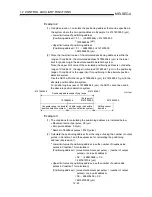
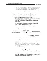
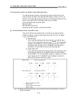
(3) Since the upper and lower limit values of the calculated positioning address
are outside the range of Condition 2, use the AD75 within the positioning
range of Condition 2 ( 214748364.8 (µm) to 214748364.7 (µm)).
Setting cannot
be made
0
-214748364.8
Usable range in absolute position
detection system
-241591910.4
241591909.5
214748364.7
Setting cannot
be made
Unit:
µ
m
Zero point
2.
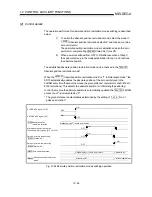
Concept in the case where the unit is degree
The positioning address is the address of the position reached by the machine
zero point return, and its range is 0° to 359.99999°.
The range 0° to 359.99999° also applies to the case where the zero point
position is not 0°.
<When the mode for absolute position restoration is the "standard mode"
("Md.121 Absolute position restoration mode" = 0)>
For positioning in the same direction, out of bound control (when the address
increases: 359.99999° 0° / when the address decreases: 0° 359.99999°)
cannot be performed.
0
Zero point
Cannot be used in the absolute
position detection system.
At power-on or reset, the current
value cannot be restored normally.
Cannot be used in the absolute
position detection system.
At power-on or reset, the current
value cannot be restored normally.
0
359.99999
359.99999
Usable range in absolute position
detection system
(0 to 359.99999 )
To make the software stroke limit valid, set the upper and lower limit values
within the range 0° to 359.99999°.
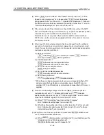
<When the mode for absolute position restoration is the "infinite length mode"
("Md.121 Absolute position restoration mode" = 1)>
For positioning in the same direction, out of bound control (when the address
increases: 359.99999° 0° / when the address decreases: 0° 359.99999°)
can be performed.
Out of bound positioning control
be performed.
(Infinite length positioning control)
Zero point
359.99999
359.99999
0
0
Make the software stroke limit invalid.
For details of the mode for absolute position restoration, refer to section "12.6.2
Absolute position restoration mode switching function".
Содержание A1SD75M1
Страница 2: ......
Страница 20: ...A 18 MEMO...
Страница 22: ...MEMO...
Страница 27: ...1 5 MELSEC A 1 PRODUCT OUTLINE MEMO...
Страница 42: ...1 20 MELSEC A 1 PRODUCT OUTLINE MEMO...
Страница 52: ...2 10 MELSEC A 2 SYSTEM CONFIGURATION MEMO...
Страница 111: ...5 21 MELSEC A 5 DATA USED FOR POSITIONING CONTROL MEMO...
Страница 115: ...5 25 MELSEC A 5 DATA USED FOR POSITIONING CONTROL MEMO...
Страница 123: ...5 33 MELSEC A 5 DATA USED FOR POSITIONING CONTROL MEMO...
Страница 127: ...5 37 MELSEC A 5 DATA USED FOR POSITIONING CONTROL MEMO...
Страница 167: ...5 77 MELSEC A 5 DATA USED FOR POSITIONING CONTROL MEMO...
Страница 193: ...5 103 MELSEC A 5 DATA USED FOR POSITIONING CONTROL MEMO...
Страница 276: ...5 186 MELSEC A 5 DATA USED FOR POSITIONING CONTROL MEMO...
Страница 332: ...7 18 MELSEC A 7 MEMORY CONFIGURATION AND DATA PROCESS MEMO...
Страница 334: ...MEMO...
Страница 422: ...9 64 MELSEC A 9 MAIN POSITIONING CONTROL MEMO...
Страница 446: ...10 24 MELSEC A 10 ADVANCED POSITIONING CONTROL MEMO...
Страница 472: ...11 26 MELSEC A 11 MANUAL CONTROL MEMO...
Страница 576: ...12 104 MELSEC A 12 CONTROL AUXILIARY FUNCTIONS MEMO...
Страница 673: ...Appendix 5 MELSEC A APPENDICES Axis address mm inch degree pulse Axis address mm inch degree pulse...
Страница 679: ...Appendix 11 MELSEC A APPENDICES Initial value Axis 1 Axis 2 Axis 3 Remarks 0 0 0 1 1 0 0 0 0 0 300 0 0 0...
Страница 683: ...Appendix 15 MELSEC A APPENDICES Initial value Axis 1 Axis 2 Axis 3 Remarks 0 0 1 0 0 50 80 0 0 980...
Страница 691: ...Appendix 23 MELSEC A APPENDICES Initial value Axis 1 Axis 2 Axis 3 Remarks 0 0 0 0 0 50 80 0 0 0 0 0 980 4000 0...
Страница 745: ......

