5. PARAMETERS
5 - 35
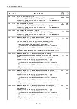
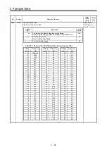
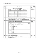
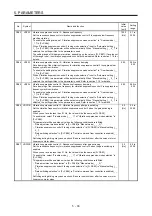
5.2.3 Extension setting parameters ([Pr. PC_ _ ])
No.
Symbol
Name and function
Initial
value
[unit]
Setting
range
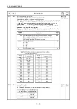
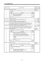
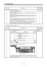
PC01
ERZ
Error excessive alarm level
Set an error excessive alarm level.
Set this per rev. for rotary servo motors and direct drive motors. Setting "0" will be 3 rev.
Setting over 200 rev will be clamped with 200 rev.
Set this per mm for linear servo motors. Setting "0" will be 100 mm.
0
[rev]/
[mm]
(Note)
0 to
1000
Note. Setting can be changed in [Pr. PC06].
PC02
MBR
Electromagnetic brake sequence output
This is used to set the delay time between MBR (Electromagnetic brake interlock) and the
base drive circuit is shut-off.
0
[ms]
0 to
1000
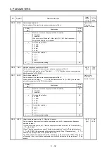
PC03
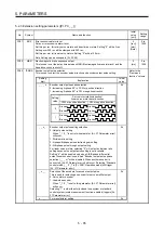
*ENRS Encoder output pulse selection
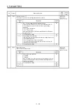
This is used to select the encoder pulse direction and encoder output pulse setting.
Refer to the
"Name and
function" column.
Setting
digit
Explanation
Initial
value
_ _ _ x
Encoder output pulse phase selection
0: Increasing A-phase 90° in CCW or positive direction
1: Increasing A-phase 90° in CW or negative direction
0h
Setting
value
Servo motor rotation direction/
linear servo motor travel direction
CCW or positive direction
CW or negative direction
0
A-phase
B-phase
A-phase
B-phase
1
A-phase
B-phase
A-phase
B-phase
_ _ x _
Encoder output pulse setting selection
0: Output pulse setting
When "_ 1 0 _" is set to this parameter, [AL. 37 Parameter error]
will occur.
1: Division ratio setting
3: A-phase/B-phase pulse electronic gear setting
4: A/B-phase pulse through output setting
For linear servo motors, selecting "0" will output as division ratio
setting because the output pulse setting is not available.
Setting "4" will be enabled only when A/B/Z-phase differential
output linear encoder is used. And "Encoder output pulse phase
selection (_ _ _ x)" will be disabled. When another encoder is
connected, [AL. 37 Parameter error] will occur. Selecting "Standard
control mode (_ _ 0 _)" in [Pr. PA01 Operation mode] will trigger
[AL. 37 Parameter error].
0h
_ x _ _
Selection of the encoders for encoder output pulse
This is used for selecting an encoder for servo amplifier output.
0: Servo motor encoder
1: Load-side encoder
When "_ 1 0 _" is set to this parameter, [AL. 37 Parameter error]
will occur.
Selecting "1" in other than fully closed loop system or standard
control system (scale measurement function: enabled) triggers [AL.
37 Parameter error].
0h
x _ _ _
For manufacturer setting
0h
Содержание MR-J4-100B(-RJ)
Страница 17: ...8 MEMO ...
Страница 143: ...4 STARTUP 4 20 MEMO ...
Страница 199: ...5 PARAMETERS 5 56 MEMO ...
Страница 227: ...6 NORMAL GAIN ADJUSTMENT 6 28 MEMO ...
Страница 281: ...8 TROUBLESHOOTING 8 16 MEMO ...
Страница 303: ...9 DIMENSIONS 9 22 MEMO ...
Страница 319: ...10 CHARACTERISTICS 10 16 MEMO ...
Страница 429: ...11 OPTIONS AND PERIPHERAL EQUIPMENT 11 110 MEMO ...
Страница 435: ...12 ABSOLUTE POSITION DETECTION SYSTEM 12 6 MEMO ...
Страница 483: ...14 USING A LINEAR SERVO MOTOR 14 34 MEMO ...
Страница 531: ...16 FULLY CLOSED LOOP SYSTEM 16 26 MEMO ...
Страница 613: ...17 APPLICATION OF FUNCTIONS 17 82 MEMO ...
Страница 653: ...APPENDIX App 40 This certificate is valid until 2017 02 28 After March 2017 use certificate shown on the previous page ...
Страница 654: ...APPENDIX App 41 ...

