


1. FUNCTIONS AND CONFIGURATION
1 - 26
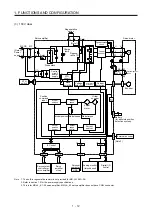
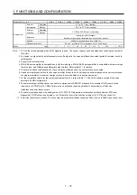
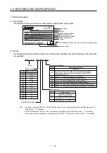
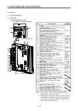
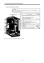
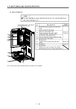
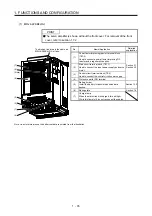
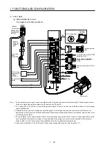
(c) MR-J4-500B(-RJ)
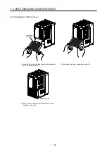
POINT
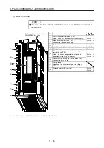
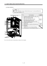
The servo amplifier is shown with the front cover open. The front cover cannot
be removed.
(1)
(3)
(2)
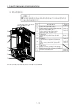
(Note)
(8)
(4)
Side
(5)
(6)
(7)
The broken line area is the same as
MR-J4-200B(-RJ) or less.
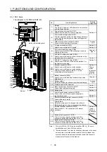
No. Name/Application
Detailed
explanation
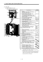
(1)
Control circuit terminal block (TE2)
Used to connect the control circuit power supply.
Section 3.1
Section 3.3
(2)
Main circuit terminal block (TE1)
Connect the input power supply.
(3)
Battery holder
Install the battery for absolute position data backup.
Section
12.2
(4) Rating plate
Section 1.6
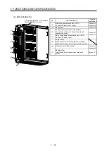
(5)
Regenerative option/power factor improving reactor
terminal block (TE3)
Used to a connect a regenerative option and a
power factor improving DC reactor.
Section 3.1
Section 3.3
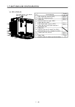
(6)
Servo motor power supply terminal block (TE4)
Connect the servo motor.
(7)
Charge lamp
When the main circuit is charged, this will light.
While this lamp is lit, do not reconnect the cables.
(8)
Protective earth (PE) terminal
Section 3.1
Section 3.3
Note. Lines for slots around the battery holder are omitted from the illustration.
Содержание MR-J4-100B(-RJ)
Страница 17: ...8 MEMO ...
Страница 143: ...4 STARTUP 4 20 MEMO ...
Страница 199: ...5 PARAMETERS 5 56 MEMO ...
Страница 227: ...6 NORMAL GAIN ADJUSTMENT 6 28 MEMO ...
Страница 281: ...8 TROUBLESHOOTING 8 16 MEMO ...
Страница 303: ...9 DIMENSIONS 9 22 MEMO ...
Страница 319: ...10 CHARACTERISTICS 10 16 MEMO ...
Страница 429: ...11 OPTIONS AND PERIPHERAL EQUIPMENT 11 110 MEMO ...
Страница 435: ...12 ABSOLUTE POSITION DETECTION SYSTEM 12 6 MEMO ...
Страница 483: ...14 USING A LINEAR SERVO MOTOR 14 34 MEMO ...
Страница 531: ...16 FULLY CLOSED LOOP SYSTEM 16 26 MEMO ...
Страница 613: ...17 APPLICATION OF FUNCTIONS 17 82 MEMO ...
Страница 653: ...APPENDIX App 40 This certificate is valid until 2017 02 28 After March 2017 use certificate shown on the previous page ...
Страница 654: ...APPENDIX App 41 ...