

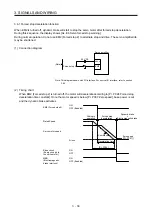


3. SIGNALS AND WIRING
3 - 18
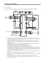
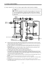
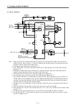
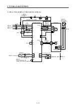
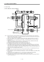
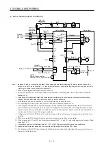
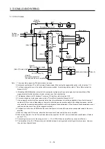
3.3 Explanation of power supply system
3.3.1 Signal explanations
POINT
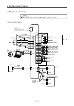
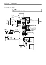
For the layout of connector and terminal block, refer to chapter 9 DIMENSIONS.
When using the MR-J4-_B-RJ servo amplifier with the DC power supply input,
refer to app. 15.
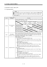
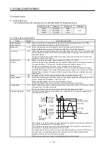
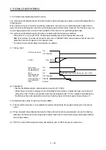
Symbol
Connection target
(application)
Description
L1/L2/L3
Main circuit power
supply
Supply the following power to L1, L2, and L3. For 1-phase 200 V AC to 240 V AC, connect the
power supply to L1 and L3. Leave L2 open.
Servo
amplifier
Power
MR-J4-10B
(-RJ) to
MR-J4-200B
(-RJ)
MR-J4-350B
(-RJ) to
MR-J4-22KB
(-RJ)
MR-J4-60B4
(-RJ) to
MR-J4-22KB4
(-RJ)
MR-J4-10B1 to
MR-J4-40B1
3-phase 200 V AC to
240 V AC, 50 Hz/60 Hz
L1/L2/L3
1-phase 200 V AC to
240 V AC, 50 Hz/60 Hz
L1/L3
3-phase 380 V AC to
480 V AC, 50 Hz/60 Hz
L1/L2/L3
1-phase 100 V AC to
120 V AC, 50 Hz/60 Hz
L1/L2
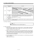
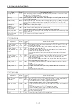
P3/P4
Power factor
improving DC reactor
When not using the power factor improving DC reactor, connect P3 and P4. (factory-wired)
When using the power factor improving DC reactor, disconnect P3 and P4, and connect the
power factor improving DC reactor to P3 and P4. Additionally, the power factor improving DC
reactor cannot be used for the 100 V class servo amplifiers.
Refer to section 11.11 for details.
P+/C/D Regenerative
option
(1) 200 V class/100 V class
1) MR-J4-500B(-RJ) or less and MR-J4-40B1(-RJ) or less
When using a servo amplifier built-in regenerative resistor, connect P+ and D. (factory-
wired)
When using a regenerative option, disconnect P+ and D, and connect the regenerative
option to P+ and C.
2) MR-J4-700B(-RJ) to MR-J4-22KB(-RJ)
MR-J4-700B(-RJ) to MR-J4-22KB(-RJ) do not have D.
When using a servo amplifier built-in regenerative resistor, connect P+ and C. (factory-
wired)
When using a regenerative option, disconnect wires of P+ and C for the built-in
regenerative resistor. And then connect wires of the regenerative option to P+ and C.
(2) 400 V class
1) MR-J4-350B4(-RJ) or less
When using a servo amplifier built-in regenerative resistor, connect P+ and D. (factory-
wired)
When using a regenerative option, disconnect P+ and D, and connect the regenerative
option to P+ and C.
2) MR-J4-500B4(-RJ) to MR-J4-22KB4(-RJ)
MR-J4-500B4(-RJ) to MR-J4-22KB4(-RJ) do not have D.
When using a servo amplifier built-in regenerative resistor, connect P+ and C. (factory-
wired)
When using a regenerative option, disconnect wires of P+ and C for the built-in
regenerative resistor. And then connect wires of the regenerative option to P+ and C.
Refer to section 11.2 for details.
Содержание MR-J4-100B(-RJ)
Страница 17: ...8 MEMO ...
Страница 143: ...4 STARTUP 4 20 MEMO ...
Страница 199: ...5 PARAMETERS 5 56 MEMO ...
Страница 227: ...6 NORMAL GAIN ADJUSTMENT 6 28 MEMO ...
Страница 281: ...8 TROUBLESHOOTING 8 16 MEMO ...
Страница 303: ...9 DIMENSIONS 9 22 MEMO ...
Страница 319: ...10 CHARACTERISTICS 10 16 MEMO ...
Страница 429: ...11 OPTIONS AND PERIPHERAL EQUIPMENT 11 110 MEMO ...
Страница 435: ...12 ABSOLUTE POSITION DETECTION SYSTEM 12 6 MEMO ...
Страница 483: ...14 USING A LINEAR SERVO MOTOR 14 34 MEMO ...
Страница 531: ...16 FULLY CLOSED LOOP SYSTEM 16 26 MEMO ...
Страница 613: ...17 APPLICATION OF FUNCTIONS 17 82 MEMO ...
Страница 653: ...APPENDIX App 40 This certificate is valid until 2017 02 28 After March 2017 use certificate shown on the previous page ...
Страница 654: ...APPENDIX App 41 ...


