

11. OPTIONS AND PERIPHERAL EQUIPMENT
11 - 66
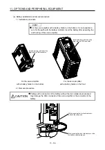
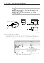
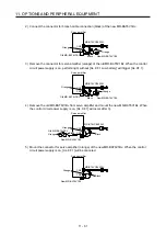
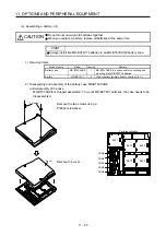
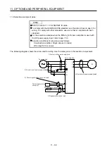
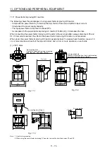
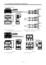
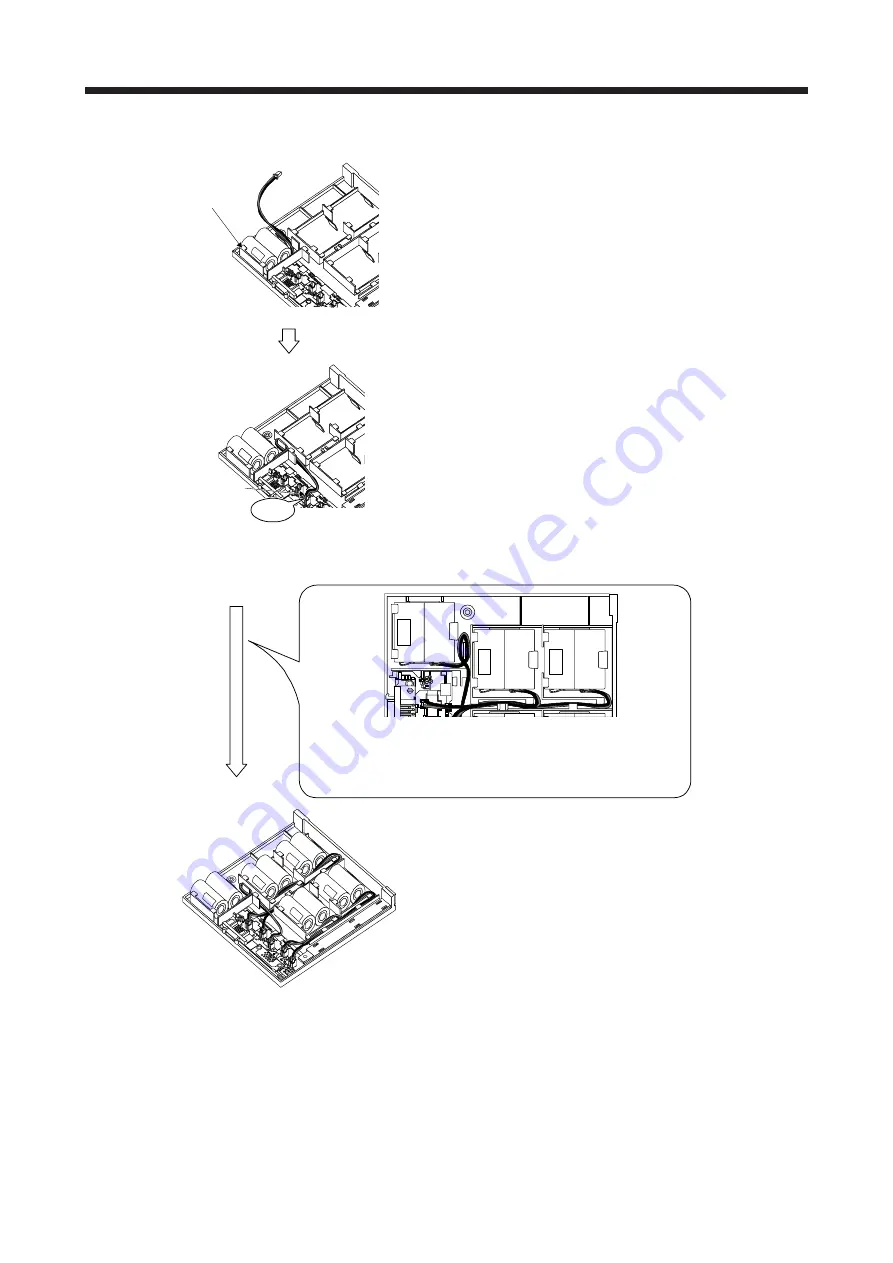
b) Mounting MR-BAT6V1
BAT1
Securely mount a MR-BAT6V1 to the BAT1 holder.
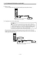
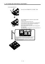
CON1
Click
Insert the MR-BAT6V1 connector mounted on BAT1
holder to CON1.
Confirm the click sound at this point.
The connector has to be connected in the right direction.
If the connector is pushed forcefully in the incorrect
direction, the connector will break.
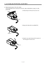
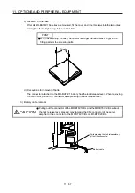
Place the MR-BAT6V1 lead wire to the duct designed to
store lead wires.
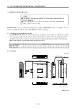
Insert MR-BAT6V1 to the holder in the same procedure in
the order from BAT2 to BAT5.
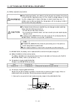
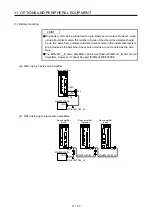
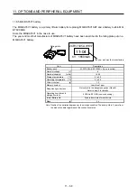
Bring out the lead wire from the space between the ribs, and bend it as
shown above to store it in the duct. Connect the lead wire to the
connector. Be careful not to get the lead wire caught in the case or
other parts.
When the lead wire is damaged, external short circuit may occur, and
the battery can become hot.
Содержание MR-J4-100B(-RJ)
Страница 17: ...8 MEMO ...
Страница 143: ...4 STARTUP 4 20 MEMO ...
Страница 199: ...5 PARAMETERS 5 56 MEMO ...
Страница 227: ...6 NORMAL GAIN ADJUSTMENT 6 28 MEMO ...
Страница 281: ...8 TROUBLESHOOTING 8 16 MEMO ...
Страница 303: ...9 DIMENSIONS 9 22 MEMO ...
Страница 319: ...10 CHARACTERISTICS 10 16 MEMO ...
Страница 429: ...11 OPTIONS AND PERIPHERAL EQUIPMENT 11 110 MEMO ...
Страница 435: ...12 ABSOLUTE POSITION DETECTION SYSTEM 12 6 MEMO ...
Страница 483: ...14 USING A LINEAR SERVO MOTOR 14 34 MEMO ...
Страница 531: ...16 FULLY CLOSED LOOP SYSTEM 16 26 MEMO ...
Страница 613: ...17 APPLICATION OF FUNCTIONS 17 82 MEMO ...
Страница 653: ...APPENDIX App 40 This certificate is valid until 2017 02 28 After March 2017 use certificate shown on the previous page ...
Страница 654: ...APPENDIX App 41 ...