13. USING STO FUNCTION
13 - 11
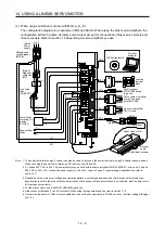
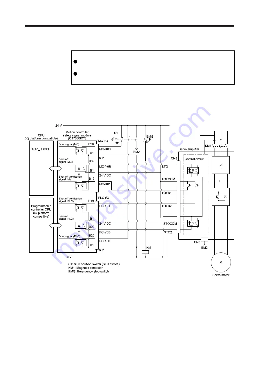
13.3.4 External I/O signal connection example using a motion controller
POINT
This connection is for source interface. For the other I/O signals, refer to the
connection examples in section 3.2.2.
For MC-Y0B and PC-Y0B, design a sequence program to output MC-Y0B and
PC-Y0B after the servo motor stops.
This connection diagram is an example of STO circuit configured with a servo amplifier and motion
controller. Use the switch that complies with the requirement of ISO/EN ISO 13849-1 Category 3 PL d as an
emergency stop switch. This connection example complies with the requirement of ISO/EN ISO 13849-1
Category 3 PL d. The following shows an example of I/O (X and Y) signal assignment of the motion
controller safety signal module. For details, refer to the motion controller user’s manual.
Содержание MR-J4-100B(-RJ)
Страница 17: ...8 MEMO ...
Страница 143: ...4 STARTUP 4 20 MEMO ...
Страница 199: ...5 PARAMETERS 5 56 MEMO ...
Страница 227: ...6 NORMAL GAIN ADJUSTMENT 6 28 MEMO ...
Страница 281: ...8 TROUBLESHOOTING 8 16 MEMO ...
Страница 303: ...9 DIMENSIONS 9 22 MEMO ...
Страница 319: ...10 CHARACTERISTICS 10 16 MEMO ...
Страница 429: ...11 OPTIONS AND PERIPHERAL EQUIPMENT 11 110 MEMO ...
Страница 435: ...12 ABSOLUTE POSITION DETECTION SYSTEM 12 6 MEMO ...
Страница 483: ...14 USING A LINEAR SERVO MOTOR 14 34 MEMO ...
Страница 531: ...16 FULLY CLOSED LOOP SYSTEM 16 26 MEMO ...
Страница 613: ...17 APPLICATION OF FUNCTIONS 17 82 MEMO ...
Страница 653: ...APPENDIX App 40 This certificate is valid until 2017 02 28 After March 2017 use certificate shown on the previous page ...
Страница 654: ...APPENDIX App 41 ...


