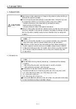
5. PARAMETERS
5 - 3
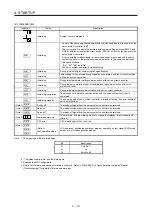
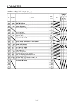
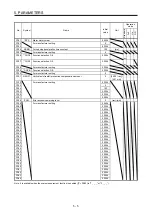
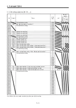
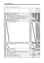
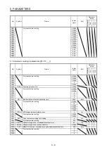
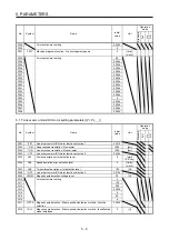
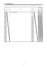
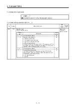
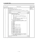
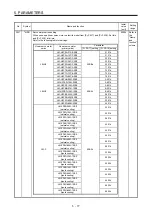
5.1.2 Gain/filter setting parameters ([Pr. PB_ _ ])
No. Symbol
Name
Initial
value
Unit
Operation
mode
Standard
F
ull.
Lin.
D.D.
PB01
FILT
Adaptive tuning mode (adaptive filter II)
0000h
PB02
VRFT
Vibration suppression control tuning mode (advanced vibration
suppression control II)
0000h
PB03 TFBGN Torque feedback loop gain
18000
[rad/s]
PB04
FFC
Feed forward gain
0
[%]
PB05
For manufacturer setting
500
PB06
GD2
Load to motor inertia ratio/load to motor mass ratio
7.00
[Multiplier]
PB07
PG1
Model loop gain
15.0
[rad/s]
PB08
PG2
Position loop gain
37.0
[rad/s]
PB09
VG2
Speed loop gain
823
[rad/s]
PB10
VIC
Speed integral compensation
33.7
[ms]
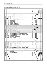
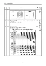
PB11
VDC
Speed differential compensation
980
PB12
OVA
Overshoot amount compensation
0
[%]
PB13
NH1
Machine resonance suppression filter 1
4500
[Hz]
PB14
NHQ1
Notch shape selection 1
0000h
PB15
NH2
Machine resonance suppression filter 2
4500
[Hz]
PB16
NHQ2
Notch shape selection 2
0000h
PB17
NHF
Shaft resonance suppression filter
0000h
PB18
LPF
Low-pass filter setting
3141
[rad/s]
PB19
VRF11 Vibration suppression control 1 - Vibration frequency
100.0
[Hz]
PB20
VRF12 Vibration suppression control 1 - Resonance frequency
100.0
[Hz]
PB21
VRF13 Vibration suppression control 1 - Vibration frequency damping
0.00
PB22
VRF14 Vibration suppression control 1 - Resonance frequency damping
0.00
PB23
VFBF
Low-pass filter selection
0000h
PB24
*MVS
Slight vibration suppression control
0000h
PB25
*BOP1 Function selection B-1
0000h
PB26
*CDP
Gain switching function
0000h
PB27
CDL
Gain switching condition
10
[kpulse/s]/
[pulse]/
[r/min]
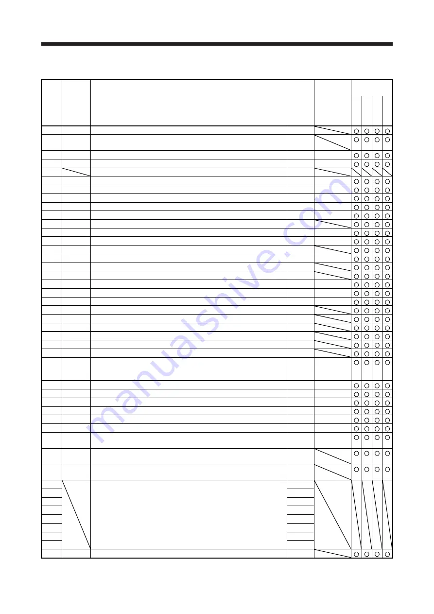
PB28
CDT
Gain switching time constant
1
[ms]
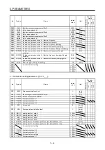
PB29
GD2B
Load to motor inertia ratio/load to motor mass ratio after gain switching
7.00
[Multiplier]
PB30
PG2B
Position loop gain after gain switching
0.0
[rad/s]
PB31
VG2B
Speed loop gain after gain switching
0
[rad/s]
PB32
VICB
Speed integral compensation after gain switching
0.0
[ms]
PB33 VRF11B Vibration suppression control 1 - Vibration frequency after gain switching
0.0
[Hz]
PB34 VRF12B Vibration suppression control 1 - Resonance frequency after gain
switching
0.0 [Hz]
PB35 VRF13B Vibration suppression control 1 - Vibration frequency damping after gain
switching
0.00
PB36 VRF14B Vibration suppression control 1 - Resonance frequency damping after
gain switching
0.00
PB37 For manufacturer setting
1600
PB38
0.00
PB39
0.00
PB40
0.00
PB41
0
PB42
0
PB43
0000h
PB44
0.00
PB45
CNHF
Command notch filter
0000h
Содержание MR-J4-100B(-RJ)
Страница 17: ...8 MEMO ...
Страница 143: ...4 STARTUP 4 20 MEMO ...
Страница 199: ...5 PARAMETERS 5 56 MEMO ...
Страница 227: ...6 NORMAL GAIN ADJUSTMENT 6 28 MEMO ...
Страница 281: ...8 TROUBLESHOOTING 8 16 MEMO ...
Страница 303: ...9 DIMENSIONS 9 22 MEMO ...
Страница 319: ...10 CHARACTERISTICS 10 16 MEMO ...
Страница 429: ...11 OPTIONS AND PERIPHERAL EQUIPMENT 11 110 MEMO ...
Страница 435: ...12 ABSOLUTE POSITION DETECTION SYSTEM 12 6 MEMO ...
Страница 483: ...14 USING A LINEAR SERVO MOTOR 14 34 MEMO ...
Страница 531: ...16 FULLY CLOSED LOOP SYSTEM 16 26 MEMO ...
Страница 613: ...17 APPLICATION OF FUNCTIONS 17 82 MEMO ...
Страница 653: ...APPENDIX App 40 This certificate is valid until 2017 02 28 After March 2017 use certificate shown on the previous page ...
Страница 654: ...APPENDIX App 41 ...