5. PARAMETERS
5 - 24
No.
Symbol
Name and function
Initial
value
[unit]
Setting
range
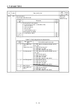
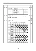
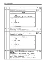
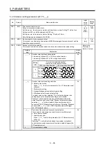
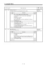
PB11
VDC
Speed differential compensation
This is used to set the differential compensation.
To enable the parameter, select "Continuous PID control enabled (_ _ 3 _)" of "PI-PID
switching control selection" in [Pr. PB24].
980 0
to
1000
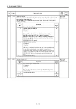
PB12
OVA
Overshoot amount compensation
Set a viscous friction torque in percentage to the rated torque at servo motor rated speed. Or,
set a percentage of viscous friction force against the continuous thrust at linear servo motor
rated speed.
When the response level is low or when the torque/thrust is limited, the efficiency of the
parameter may be lower.
0
[%]
0 to 100
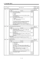
PB13
NH1
Machine resonance suppression filter 1
Set the notch frequency of the machine resonance suppression filter 1.
When "Filter tuning mode selection" is set to "Automatic setting (_ _ _ 1)" in [Pr. PB01], this
parameter will be adjusted automatically by adaptive tuning.
When "Filter tuning mode selection" is set to "Manual setting (_ _ _ 2)" in [Pr. PB01],the
setting value will be enabled.
4500
[Hz]
10
to
4500
PB14
NHQ1
Notch shape selection 1
Set the shape of the machine resonance suppression filter 1.
When "Filter tuning mode selection" is set to "Automatic setting (_ _ _ 1)" in [Pr. PB01], this
parameter will be adjusted automatically by adaptive tuning.
To enable the setting value, select the manual setting.
Refer to the
"Name and
function" column.
Setting
digit
Explanation
Initial
value
_ _ _ x
For manufacturer setting
0h
_ _ x _
Notch depth selection
0: -40 dB
1: -14 dB
2: -8 dB
3: -4 dB
0h
_ x _ _
Notch width selection
0:
α
= 2
1:
α
= 3
2:
α
= 4
3:
α
= 5
0h
x _ _ _
For manufacturer setting
0h
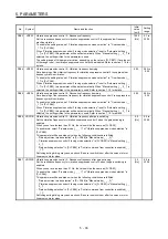
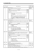
PB15
NH2
Machine resonance suppression filter 2
Set the notch frequency of the machine resonance suppression filter 2.
To enable the setting value, select "Enabled (_ _ _ 1)" of "Machine resonance suppression
filter 2 selection" in [Pr. PB16].
4500
[Hz]
10
to
4500
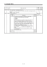
PB16
NHQ2
Notch shape selection 2
Set the shape of the machine resonance suppression filter 2.
Refer to the
"Name and
function" column.
Setting
digit
Explanation
Initial
value
_ _ _ x
Machine resonance suppression filter 2 selection
0: Disabled
1: Enabled
0h
_ _ x _
Notch depth selection
0: -40 dB
1: -14 dB
2: -8 dB
3: -4 dB
0h
_ x _ _
Notch width selection
0:
α
= 2
1:
α
= 3
2:
α
= 4
3:
α
= 5
0h
x _ _ _
For manufacturer setting
0h
Содержание MR-J4-100B(-RJ)
Страница 17: ...8 MEMO ...
Страница 143: ...4 STARTUP 4 20 MEMO ...
Страница 199: ...5 PARAMETERS 5 56 MEMO ...
Страница 227: ...6 NORMAL GAIN ADJUSTMENT 6 28 MEMO ...
Страница 281: ...8 TROUBLESHOOTING 8 16 MEMO ...
Страница 303: ...9 DIMENSIONS 9 22 MEMO ...
Страница 319: ...10 CHARACTERISTICS 10 16 MEMO ...
Страница 429: ...11 OPTIONS AND PERIPHERAL EQUIPMENT 11 110 MEMO ...
Страница 435: ...12 ABSOLUTE POSITION DETECTION SYSTEM 12 6 MEMO ...
Страница 483: ...14 USING A LINEAR SERVO MOTOR 14 34 MEMO ...
Страница 531: ...16 FULLY CLOSED LOOP SYSTEM 16 26 MEMO ...
Страница 613: ...17 APPLICATION OF FUNCTIONS 17 82 MEMO ...
Страница 653: ...APPENDIX App 40 This certificate is valid until 2017 02 28 After March 2017 use certificate shown on the previous page ...
Страница 654: ...APPENDIX App 41 ...

