


5. PARAMETERS
5 - 41
No.
Symbol
Name and function
Initial
value
[unit]
Setting
range
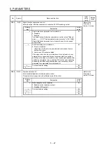
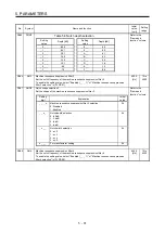
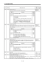
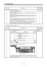
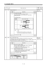
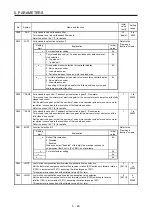
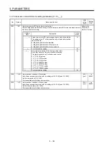
PC27 **COP9 Function selection C-9
This is used to select a polarity of the linear encoder or load-side encoder.
Refer to the
"Name and
function" column.
Setting
digit
Explanation
Initial
value
_ _ _ x
Encoder pulse count polarity selection
0: Encoder pulse increasing direction in the servo motor CCW or
positive direction
1: Encoder pulse decreasing direction in the servo motor CCW or
positive direction
0h
_ _ x _
For manufacturer setting
0h
_ x _ _
Selection of A/B/Z-phase input interface encoder Z-phase
connection judgment function
This is used to select a non-signal detection of A/B/Z-phase input
interface encoder pulse train signal used as linear encoder or load-
side encoder.
This digit is enabled only when you use an A/B/Z-phase input
interface encoder.
0h
Setting
value
Detection of
disconnection
Alarm status
Z-phase-side
non-signal
Standard (scale
measurement
enabled)
Fully closed
loop system
Linear servo
system
0 Enabled
[AL. 71.6]
(Z-phase)
[AL. 71.6]
(Z-phase)
[AL. 20.6]
(Z-phase)
1 Disabled
x _ _ _
For manufacturer setting
0h
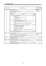
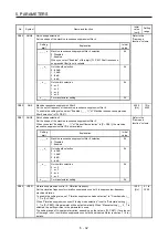
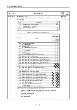
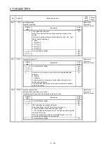
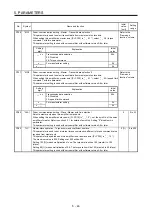
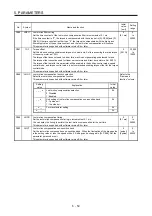
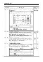
PC29 *COPB Function selection C-B
This is used to select the POL reflection at torque control.
Refer to the
"Name and
function" column.
Setting
digit
Explanation
Initial
value
_ _ _ x
For manufacturer setting
0h
_ _ x _
0h
_ x _ _
0h
x _ _ _
POL reflection selection at torque control
0: Enabled
1: Disabled
0h
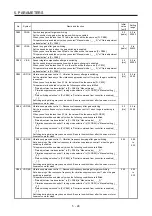
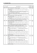
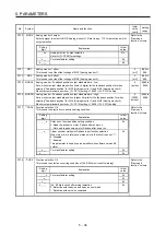
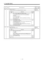
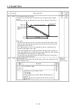
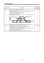
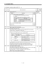
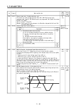
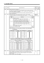
PC31 RSUP1 Vertical axis freefall prevention compensation amount
Set the compensation amount of the vertical axis freefall prevention function.
Set it per servo motor rotation amount or linear servo motor travel distance.
When a positive value is set, compensation is performed to the address increasing direction.
When a negative value is set, compensation is performed to the address decreasing direction.
The vertical axis freefall prevention function is performed when all of the following conditions
are met.
1) Position control mode
2) The value of the parameter is other than "0".
3) The forced stop deceleration function is enabled.
4) Alarm occurs or EM2 turns off when the (linear) servo motor speed is zero speed or less.
5) MBR (Electromagnetic brake interlock) was enabled in [Pr. PD07] to [Pr. PD09], and the
base circuit shut-off delay time was set in [Pr. PC02].
0
[0.0001
rev]/
[0.01 mm]
-25000
to
25000
Содержание MR-J4-100B(-RJ)
Страница 17: ...8 MEMO ...
Страница 143: ...4 STARTUP 4 20 MEMO ...
Страница 199: ...5 PARAMETERS 5 56 MEMO ...
Страница 227: ...6 NORMAL GAIN ADJUSTMENT 6 28 MEMO ...
Страница 281: ...8 TROUBLESHOOTING 8 16 MEMO ...
Страница 303: ...9 DIMENSIONS 9 22 MEMO ...
Страница 319: ...10 CHARACTERISTICS 10 16 MEMO ...
Страница 429: ...11 OPTIONS AND PERIPHERAL EQUIPMENT 11 110 MEMO ...
Страница 435: ...12 ABSOLUTE POSITION DETECTION SYSTEM 12 6 MEMO ...
Страница 483: ...14 USING A LINEAR SERVO MOTOR 14 34 MEMO ...
Страница 531: ...16 FULLY CLOSED LOOP SYSTEM 16 26 MEMO ...
Страница 613: ...17 APPLICATION OF FUNCTIONS 17 82 MEMO ...
Страница 653: ...APPENDIX App 40 This certificate is valid until 2017 02 28 After March 2017 use certificate shown on the previous page ...
Страница 654: ...APPENDIX App 41 ...