


11. OPTIONS AND PERIPHERAL EQUIPMENT
11 - 83
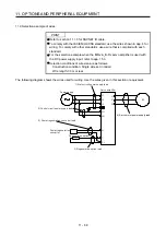
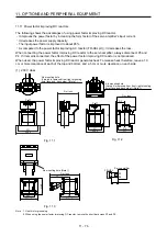
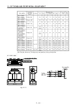
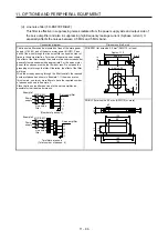
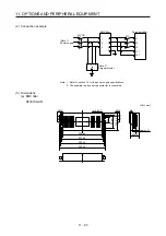
Instrument
Receiver
Servo
amplifier
Servo motor
M
2)
2)
8)
1)
7)
7)
7)
5)
3)
4)
6)
3)
Sensor
power
supply
Sensor
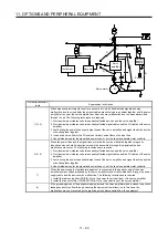
Noise transmission
route
Suppression techniques
1) 2) 3)
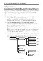
When measuring instruments, receivers, sensors, etc. which handle weak signals and may
malfunction due to noise and/or their signal cables are contained in a cabinet together with the servo
amplifier or run near the servo amplifier, such devices may malfunction due to noises transmitted
through the air. The following techniques are required.
1. Provide maximum clearance between easily affected devices and the servo amplifier.
2. Provide maximum clearance between easily affected signal cables and the I/O cables of the servo
amplifier.
3. Avoid wiring the power lines (input/output lines of the servo amplifier) and signal lines side by side
or bundling them together.
4. Insert a line noise filter to the I/O cables or a radio noise filter on the input line.
5. Use shielded wires for the signal and power lines, or put the lines in separate metal conduits.
4) 5) 6)
When the power lines and the signal lines are laid side by side or bundled together, magnetic
induction noise and static induction noise will be transmitted through the signal cables and
malfunction may occur. The following techniques are required.
1. Provide maximum clearance between easily affected devices and the servo amplifier.
2. Provide maximum clearance between easily affected signal cables and the I/O cables of the servo
amplifier.
3. Avoid wiring the power lines (input/output lines of the servo amplifier) and signal lines side by side
or bundling them together.
4. Use shielded wires for the signal and power lines, or put the lines in separate metal conduits.
7)
When the power supply of peripheral equipment is connected to the power supply of the servo
amplifier system, noises produced by the servo amplifier may be transmitted back through the power
supply cable and the devices may malfunction. The following techniques are required.
1. Install the radio noise filter (FR-BIF(-H)) on the power lines (Input lines) of the servo amplifier.
2. Install the line noise filter (FR-BSF01/FR-BLF) on the power lines of the servo amplifier.
8)
If the grounding wires of the peripheral equipment and the servo amplifier make a closed loop circuit,
leakage current may flow through, causing the equipment to malfunction. In this case, the
malfunction may be prevented by the grounding wires disconnected from the equipment.
Содержание MR-J4-100B(-RJ)
Страница 17: ...8 MEMO ...
Страница 143: ...4 STARTUP 4 20 MEMO ...
Страница 199: ...5 PARAMETERS 5 56 MEMO ...
Страница 227: ...6 NORMAL GAIN ADJUSTMENT 6 28 MEMO ...
Страница 281: ...8 TROUBLESHOOTING 8 16 MEMO ...
Страница 303: ...9 DIMENSIONS 9 22 MEMO ...
Страница 319: ...10 CHARACTERISTICS 10 16 MEMO ...
Страница 429: ...11 OPTIONS AND PERIPHERAL EQUIPMENT 11 110 MEMO ...
Страница 435: ...12 ABSOLUTE POSITION DETECTION SYSTEM 12 6 MEMO ...
Страница 483: ...14 USING A LINEAR SERVO MOTOR 14 34 MEMO ...
Страница 531: ...16 FULLY CLOSED LOOP SYSTEM 16 26 MEMO ...
Страница 613: ...17 APPLICATION OF FUNCTIONS 17 82 MEMO ...
Страница 653: ...APPENDIX App 40 This certificate is valid until 2017 02 28 After March 2017 use certificate shown on the previous page ...
Страница 654: ...APPENDIX App 41 ...