15. USING A DIRECT DRIVE MOTOR
15 - 9
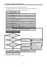
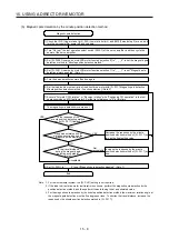
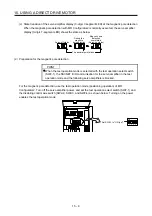
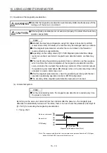
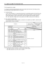
(c) State transition of the servo amplifier display (3-digit, 7-segment LED) at the magnetic pole detection
When the magnetic pole detection with MR Configurator2 is normally executed, the servo amplifier
display (3-digit, 7-segment LED) shows the state as below.
The decimal point blinks.
Servo-off status
During the
magnetic
pole detection
Magnetic pole
detection
completed
(Servo-on status)
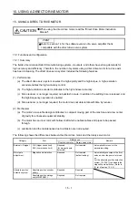
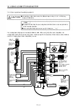
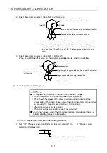
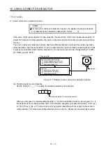
(2) Preparation for the magnetic pole detection
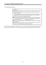
POINT
When the test operation mode is selected with the test operation select switch
(SW2-1), the SSCNET III/H communication for the servo amplifier in the test
operation mode and the following servo amplifiers is blocked.
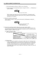
For the magnetic pole detection, use the test operation mode (positioning operation) of MR
Configurator2. Turn off the servo amplifier power, and set the test operation select switch (SW2-1) and
the disabling control axis switch (SW2-2, SW2-3, and SW2-4) as shown below. Turning on the power
enables the test operation mode.
Set SW2-1 to "ON (up)".
1
ON
2 3 4
Содержание MR-J4-100B(-RJ)
Страница 17: ...8 MEMO ...
Страница 143: ...4 STARTUP 4 20 MEMO ...
Страница 199: ...5 PARAMETERS 5 56 MEMO ...
Страница 227: ...6 NORMAL GAIN ADJUSTMENT 6 28 MEMO ...
Страница 281: ...8 TROUBLESHOOTING 8 16 MEMO ...
Страница 303: ...9 DIMENSIONS 9 22 MEMO ...
Страница 319: ...10 CHARACTERISTICS 10 16 MEMO ...
Страница 429: ...11 OPTIONS AND PERIPHERAL EQUIPMENT 11 110 MEMO ...
Страница 435: ...12 ABSOLUTE POSITION DETECTION SYSTEM 12 6 MEMO ...
Страница 483: ...14 USING A LINEAR SERVO MOTOR 14 34 MEMO ...
Страница 531: ...16 FULLY CLOSED LOOP SYSTEM 16 26 MEMO ...
Страница 613: ...17 APPLICATION OF FUNCTIONS 17 82 MEMO ...
Страница 653: ...APPENDIX App 40 This certificate is valid until 2017 02 28 After March 2017 use certificate shown on the previous page ...
Страница 654: ...APPENDIX App 41 ...


