


3. SIGNALS AND WIRING
3 - 26
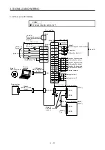
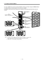
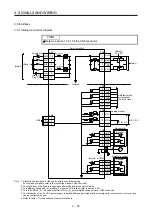
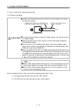
3.5 Signal (device) explanations
For the I/O interfaces (symbols in I/O division column in the table), refer to section 3.8.2.
The pin numbers in the connector pin No. column are those in the initial status.
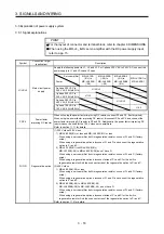
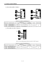
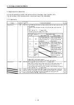
3.5.1 Input device
Device Symbol
Connector
pin No.
Function and application
I/O
division
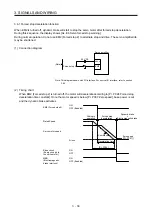
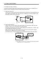
Forced stop 2
EM2
CN3-20 Turn off EM2 (open between commons) to decelerate the servo motor to a stop
with commands.
Turn EM2 on (short between commons) in the forced stop state to reset that
state.
Set [Pr. PA04] to "2 1 _ _" to disable EM2.
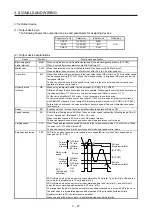
The following shows the setting of [Pr. PA04].
DI-1
[Pr. PA04]
setting
EM2/EM1
Deceleration method
EM2 or EM1 is off
Alarm occurred
0 0 _ _
EM1
MBR (Electromagnetic
brake interlock) turns off
without the forced stop
deceleration.
MBR (Electromagnetic
brake interlock) turns off
without the forced stop
deceleration.
2 0 _ _
EM2
MBR (Electromagnetic
brake interlock) turns off
after the forced stop
deceleration.
MBR (Electromagnetic
brake interlock) turns off
after the forced stop
deceleration.
0 1 _ _
Not using
EM2 and
EM1
MBR (Electromagnetic
brake interlock) turns off
without the forced stop
deceleration.
2 1 _ _
Not using
EM2 and
EM1
MBR (Electromagnetic
brake interlock) turns off
after the forced stop
deceleration.
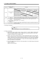
EM2 and EM1 are mutually exclusive.
EM2 has the same function as EM1 in the torque control mode.
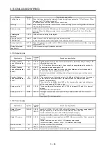
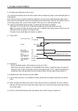
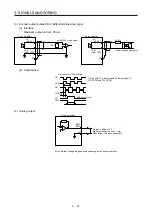
Forced stop 1
EM1
(CN3-20) When using EM1, set [Pr. PA04] to "0 0 _ _" to enable EM1.
When EM1 is turned off (open between commons), the base circuit shuts off,
and the dynamic brake operates to decelerate the servo motor to a stop.
The forced stop will be reset when EM1 is turned on (short between commons).
Set [Pr. PA04] to "0 1 _ _" to disable EM1.
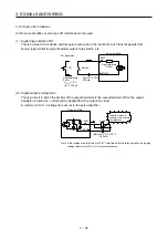
DI-1
DI1
CN3-2
Devices can be assigned for these signals with controller setting. For devices
that can be assigned, refer to the controller instruction manual. The following
devices can be assigned for MR-J4 compatible controller (R_MTCPU,
Q17_DSCPU, RD77MS_ and QD77MS_).
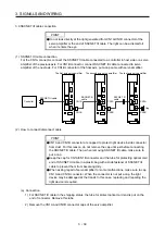
DI-1
DI2
CN3-12
DI-1
DI3
CN3-19
DI-1
Содержание MR-J4-100B(-RJ)
Страница 17: ...8 MEMO ...
Страница 143: ...4 STARTUP 4 20 MEMO ...
Страница 199: ...5 PARAMETERS 5 56 MEMO ...
Страница 227: ...6 NORMAL GAIN ADJUSTMENT 6 28 MEMO ...
Страница 281: ...8 TROUBLESHOOTING 8 16 MEMO ...
Страница 303: ...9 DIMENSIONS 9 22 MEMO ...
Страница 319: ...10 CHARACTERISTICS 10 16 MEMO ...
Страница 429: ...11 OPTIONS AND PERIPHERAL EQUIPMENT 11 110 MEMO ...
Страница 435: ...12 ABSOLUTE POSITION DETECTION SYSTEM 12 6 MEMO ...
Страница 483: ...14 USING A LINEAR SERVO MOTOR 14 34 MEMO ...
Страница 531: ...16 FULLY CLOSED LOOP SYSTEM 16 26 MEMO ...
Страница 613: ...17 APPLICATION OF FUNCTIONS 17 82 MEMO ...
Страница 653: ...APPENDIX App 40 This certificate is valid until 2017 02 28 After March 2017 use certificate shown on the previous page ...
Страница 654: ...APPENDIX App 41 ...