7 PARAMETERS
7.2 Detailed list of parameters
187
7
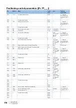
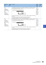
Positioning control parameters ([Pr. PT_ _ ])
No./symbol/
name
Setting
digit
Function
Initial
value
[unit]
Control
mode
CP
PS
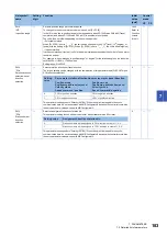
PT01
**CTY
Command mode
selection
_ _ _ x
Positioning command method selection
0: Absolute value command method
1: Incremental value command method
0h
_ _ x _
For manufacturer setting
0h
_ x _ _
Position data unit
0: mm
1: inch
2: degree
3: pulse
The setting value "2" is available with servo amplifiers with software version A6 or later. For servo
amplifiers with software version older than A6, setting "2" triggers [AL. 37.1].
3h
x _ _ _
For manufacturer setting
0h
PT03
*FTY
Feeding function
selection
_ _ _ x
Feed length multiplication (STM)
0: × 1
1: × 10
2: × 100
3: × 1000
This digit is disabled when [degree] or [pulse] is selected for "Unit for position data" in [Pr. PT01].
The unit [degree] is used with servo amplifiers with software version A6 or later.
This parameter corresponds to "Shaft revolutions (6092h: 2)". When the object is mapped to the
cyclic communication data, do not write values with MR Configurator2 because the controller
overwrites the servo parameter values written with MR Configurator2.
0h
_ _ x _
For manufacturer setting
0h
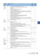
_ x _ _
Shortest rotation selection per degree
0: Rotation direction specifying
1: Shortest rotation
2: Rotation in address decreasing direction
3: Rotation in address increasing direction
This digit setting becomes valid as soon as it is changed.
This digit setting is invalid for the incremental value command method.
0h
x _ _ _
For manufacturer setting
0h
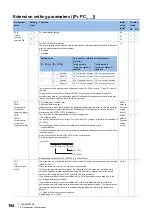
PT07
ZST
Home position
shift distance
Set a shift distance from the Z-phase pulse detection position in the encoder.
Up to 2
31-1
can be set with [Pr. PT69].
Refer to section 4.6 of "MR-J4-_GF_(-RJ) Servo Amplifier Instruction Manual (Motion Mode)" for the
home position shift direction.
The unit will be as follows depending on the positioning mode.
• Point table method
The unit can be changed to [µm], 10
-4
[inch], 10
-3
[degree], or [pulse] with the setting of [Pr. PT01].
The unit [degree] is used with servo amplifiers with software version A6 or later.
• Indexer method
It will be command unit [pulse]. (unit of a load-side rotation expressed by the number of servo motor
resolution pulses)
Refer to the Function column of [Pr. PA10] for the command unit.
Setting range: 0 to 65535
0
Refer to
Function
column
for unit.
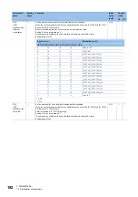
PT09
DCT
Travel distance
after proximity
dog
Set a travel distance after proximity dog at home position return for the count type (front end
detection, Z-phase reference) (Homing method -2, -34) and dog reference.
Up to 2
31
can be set with [Pr. PT71].
The following shows the home position return of the dog reference.
• Dog type rear end reference home position return (Homing method -6, -38)
• Count type home position return (Front end reference) (Homing method -7, -39)
• Dog type front end reference home position return (Homing method -10, -42)
• Homing without index pulse (Homing method 19, 20, 21, 22, 23, 24, 27, 28)
The unit can be changed to 10
STM
[
μ
m], 10
(STM-4)
[inch], 10
-3
[degree], or [pulse] with the setting of
[Pr. PT01].
The unit [degree] is used with servo amplifiers with software version A6 or later.
Setting range: 0 to 65535
0
Refer to
Function
column
for unit.

