14
1 FUNCTIONS AND CONFIGURATION
1.1 For proper use of CC-Link IE Field Network Basic
1
FUNCTIONS AND CONFIGURATION
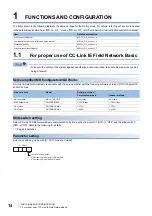
The items shown in the following table are the same as those for the motion mode. For details, refer to each section indicated
in the detailed explanation field. "MR-J4-_GF_" means "MR-J4-_GF_(-RJ) Servo Amplifier Instruction Manual (Motion Mode)".
1.1
For proper use of CC-Link IE Field Network Basic
• To ensure the safety of the system against unauthorized network access, take security measures such as
using a firewall.
Servo amplifier/MR Configurator2/GX Works
CC-Link IE Field Network Basic is available with the servo amplifier with the following software versions, MR Configurator2,
and GX Works.
Slide switch setting
Select CC-Link IE Field Network Basic communication by turning the slide switch 1 (SW1-1) "OFF" and the slide switch 2
(SW1-2) "ON". Refer to the following for details.
Parameter setting
Select a positioning mode with [Pr. PA01 Operation mode].
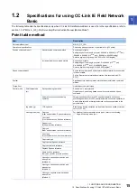
Item
Detailed explanation
Function block diagram
MR-J4-_GF_ section 1.2
Combinations of servo amplifiers and servo motors
MR-J4-_GF_ section 1.4
Model designation
MR-J4-_GF_ section 1.6
Structure (parts identification)
MR-J4-_GF_ section 1.7
Product name
Model
Software version
Point table method
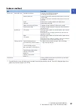
Indexer method
Servo amplifier
MR-J4-_GF_(-RJ)
A4 or later
A4 or later
MR Configurator2
SW1DNC-MRC2-_
1.70Y or later
1.70Y or later
GX Works2
SW1DNC-GXW2-J
1.570U
1.570U
GX Works3
SW1DND-GXW3-J
1.040S
1.040S
[Pr. PA01]
Control mode selection
0: Positioning mode (point table method)
8: Positioning mode (indexer method)


