20
1 FUNCTIONS AND CONFIGURATION
1.4 Function list
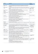
Power monitoring
function
This function calculates the power running energy and the regenerative power from the data in the
servo amplifier such as speed and current. Power consumption and others are displayed on MR
Configurator2.
Machine diagnosis
function
From the data in the servo amplifier, this function estimates the friction and vibrational component of the
drive system in the equipment and recognizes an error in the machine parts, including a ball screw and
bearing.
This function is available with MR Configurator2 or via a network.
diagnosis function
MR-J4-_GF_ section
17.5
Scale measurement
function
The function transmits position information of a scale measurement encoder to the controller by
connecting the scale measurement encoder in semi closed loop control.
MR-J4-_GF_ section
17.1
Limit switch
External limit switches can be used to limit travel intervals of the servo motor.
S-pattern acceleration/
deceleration
Enables smooth acceleration and deceleration.
Set S-pattern acceleration/deceleration time constants with [Pr. PT51].
As compared with linear acceleration/deceleration, the acceleration/deceleration time will be longer for
the S-pattern acceleration/deceleration time constants regardless of command speed.
[Pr. PT51]
Software limit
Limits travel intervals by address using parameters.
Enables the same function with the limit switch by setting parameters.
MR-J4-_GF_ section 5.3
Analog override
The servo motor speed can be changed with a link device.
It can be changed to 0% to 200% of the set speed.
This is available with servo amplifiers with software version A6 or later.
Digital override
The actual servo motor speed is the result of multiplying the command speed by the override value
selected by bits 3 to 6 (C_OV0 to C_OV3) of Control DI8 (2D08h).
It can be changed to 0% to 360% of the set speed.
This is available with servo amplifiers with software version A6 or later.
Speed limit
The servo motor speed can be limited.
Lost motion
compensation function
This function improves the response delay generated when the machine moving direction is reversed.
MR-J4-_GF_ section 7.6
Super trace control
This function sets constant and uniform acceleration/deceleration droop pulses to almost 0.
MR-J4-_GF_ section 7.7
CC-Link IE Field
Network Basic
CC-Link IE Field Network Basic enables fixed cycle communication between the master and slave
stations using a general-purpose Ethernet connector. The parameters of servo amplifiers can be set
(read/written) and monitored.
SLMP
SLMP (SeamLess Message Protocol) is a protocol to access SLMP-compatible devices from external
devices (such as a personal computer and an HMI) or programmable controller CPU via Ethernet. The
parameters of servo amplifiers can be set (read or written) and monitored.
IP address filtering
function
You can limit the network devices to be connected to the servo amplifier by registering the range of IP
addresses in advance.
Operation specification
IP address function
In Ethernet communication (CC-Link IE Field Network Basic or SLMP), to limit the network devices to
which the operation right is given, set the range of the device IP addresses.
Monitoring/parameter reading can be performed with the network devices having no operation right.
Functional safety unit
MR-D30 can be used to expand the safety observation function.
CC-Link IE Field Network Basic communication is not available. When CC-Link IE Field Network Basic
is set, connecting an MR-D30 functional safety unit triggers [AL. 3E.8].
Simple cam function
This function enables synchronous control by using software instead of controlling mechanically with
cam. This function enables the encoder following function, simple cam position compensation function,
and synchronous operation using positioning data.
The touch probe function cannot be used when "Simple cam function selection" in [Pr. PT35] is set to
"2" or "3" and cam position compensation by touch probe is enabled.
Infinite feed function
(when degree is set)
When the unit of position data for automatic operation or manual operation of the point table method is
set to degree, the detection of [AL. E3.1 Multi-revolution counter travel distance excess warning] is
disabled and the home position is retained even if the servo motor rotates 32768 revolutions or more in
the same direction.
Thus, the current position is restored after the power is cycled.
This function can be used with the absolute position detection system.
This is available with servo amplifiers with software version A6 or later.
feed function (setting
degree)
Function
Description
Detailed
explanation

