background image

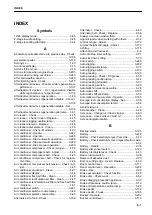
Secondary steering system pilot lamp.................. 3-37
Select suitable place for inspection and maintenance.

.......................................................................2-32

Self-check function for secondary steering......... 3-199
Service meter location.......................................... 1-16
Shift hold pilot lamp...............................................3-35
Shift indicator........................................................ 3-38
Shift lever position display.................................... 3-38
Shoulder belt and waist belt - Connect................. 6-14
Slow-blow fuse.................................................... 3-118
Slow-blow fuse - Replace..................................... 4-34
Specifications..........................................................5-2
Specifications - WA480-8........................................5-2
Speedometer........................................................ 3-41
Stability................................................................. 2-32
Standard tightening torque for bolts and nuts....... 4-10
Start engine...........................................................2-23
Start engine with jumper cables............................2-24
Starting motor - Check.......................................... 4-74
Starting motor and alternator - Overhaul.............. 4-76
Starting switch.......................................................3-92
Steering oil pressure caution lamp........................3-23
Steering system caution lamp...............................3-23
Steering tilt lock lever..........................................3-108
Stop  engine  before  performing  inspection  and  main-

tenance.......................................................... 2-33

Store oil and fuel..................................................... 4-8
Sunlight sensor................................................... 3-228
Suspension damper hardness - Adjust............... 3-172
Switch panel equipment name................................3-4
Switches................................................................3-91
System caution lamp.............................................3-20
System operating lamp....................................... 3-125

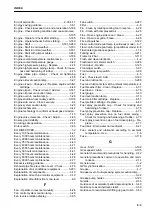
T

Target  fuel  consumption  value  displayed  in  ECO

gauge - Set.................................................... 3-58

Temperature control switch................................. 3-224
Time - Set..............................................................3-84
Tire - Handle............................................... 2-41,3-220
Tire - Select / Check..............................................4-36
Tire and bucket - Select.......................................... 6-2
Tire inflation pressure - Check............................ 3-168
Tire inflation pressure - Check and inflate.............4-37
Tire pressure.......................................................3-220
Tires...................................................................... 2-41
Tires - Select.........................................................4-36
Toolbox................................................................3-120
Torque converter lockup - Handle....................... 3-200
Torque converter lockup mode display................. 3-35
Torque converter lockup switch...........................3-102
Torque converter oil temperature caution lamp.....3-19
Torque converter oil temperature gauge............... 3-42
Towing and being towed....................................... 2-31
Towing pin - Use..................................................3-119
Towing when engine can run.............................. 3-244
Towing when engine does not run...................... 3-244

Transmission breather - Clean..............................4-55
Transmission case - Change oil / Clean strainer.. 4-53
Transmission case - Check oil level / Add oil........4-23
Transmission cut-off function.............................. 3-196
Transmission cut-off function - Apply brake........ 3-197
Transmission cut-off pilot lamp............................. 3-36
Transmission cut-off position - Adjust................. 3-196
Transmission cut-off set switch........................... 3-100
Transmission cut-off switch.................................3-100
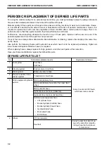
Transmission oil filter cartridge - Replace............. 4-54
Transmission serial plate location......................... 1-15
Transmission shift mode selector switch.............3-102
Transmission system caution lamp....................... 3-24
Transportation.....................................................3-232
Travel downhill.................................................... 3-205
Travel speed warning function............................ 3-201
Trip meter..............................................................3-70
Troubles and actions...........................................3-243
Turbocharger protection function........................ 3-185
Turn battery disconnect switch to off position....... 2-36
Turn off ecss switch before performing inspection and

maintenance.................................................. 2-35

Turn signal lever....................................................3-93
Turn signal pilot lamp............................................3-32
Two workers for maintenance when engine is running

.......................................................................2-34

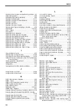
U

Unauthorized modification.................................... 2-20
Understanding the machine.................................. 2-14
Unlock knob for slide window of cab................... 3-113
Up switch.............................................................. 3-47
Urea SCR system warning - Handle................... 3-139
Use  handrails  and  steps  when  getting  on  or  off  ma-

chine.............................................................. 2-17

Use proper tools....................................................2-36
Use warning tags.................................................. 2-23
User menu............................................................ 3-48

V

V-shape loading.................................................. 3-211
Vent selector switch - Select............................... 3-225
Vibration damper - Check..................................... 4-63
Vibration level......................................................... 1-9
Visibility from operator's seat................................ 1-10

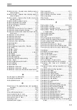
W

Warning display............................................ 3-14,3-23
Water pump - Check............................................. 4-74
Water separator - Check / Drain water and sediment..

.....................................................................3-159

Wear well-fitting clothes and protective equipment......

.......................................................................2-14

Weight and height of seat - Adjust...................... 3-170
Welding instructions................................................4-2
Wheel hub bolts - Check looseness / Retighten... 4-47

INDEX

8-7

Содержание WA480-8

Страница 1: ...is machine may be hazardous and cause injuries The operator and maintenance personnel must read this manual before commencing operation or maintenance Keep this manual within reach at all times and en...

Страница 2: ......

Страница 3: ...uine new Komatsu or Ko matsu approved rebuilt parts or assemblies or others parts of equivalent quality and that the engine be serviced by an authorized Komatsu distribu tor Failure to follow these re...

Страница 4: ...name and the serial No see the machine serial No plate In order to arrange the proper Operation and Maintenance Manual you will need to provide the machine model name and the serial No This manual use...

Страница 5: ...any subse quently installed electrical and electronic components comply with the EMV Directive 2014 30 EU in its current edition and bear the CE mark The following requirements also have to be met for...

Страница 6: ...ng the processing of your personal data i e storage collection transfer etc of all information that relates to you as operator to the party with whom you have most direct relationship In principle thi...

Страница 7: ...tion 4 above For the purposes a to l as indicated in section 4 above as well as for the purpose of informing a third party in the context of a possible merger acquisition or demerger the processing of...

Страница 8: ...t data b the processing is illegitimate or c the data are no longer needed for the pur poses which are outlined above but you need them to defend yourself in judicial proceedings You have the right to...

Страница 9: ...safety mes sage This signal word indicates an imminently hazardous situation which if not avoided will result in death or serious injury This signal word indicates a potentially hazardous situation wh...

Страница 10: ...he standard deviation of the meas ured time averaged A weighted emission sound pressure level at the operator s position is 2 5 dB in accordance with ISO 11201 Sound power level emitted by the machine...

Страница 11: ...king and traveling in good condition Remove any large rocks or obstacles Fill any ditches and holes Site manager should provide machine operators with machine and schedule time to maintain terrain con...

Страница 12: ...MMENDED APPLICATIONS 3 206 DIRECTIONS OF MACHINE A Front B Rear C Left D Right E Bucket F Operator s seat In this manual the directions of the machine front rear left right are determined according to...

Страница 13: ...2 m and 1 5 m at a 1 m away from the outside sur face of the machine and a visibility for a radius of 12 m P P P P Height to evaluate the proximity visibility Front side Left hand side Right hand sid...

Страница 14: ...in the visibility map the site operator may wish to provide additional meas ures where it is felt necessary or provide additional instruction to personnel Specification of visibility map Machine Postu...

Страница 15: ...Exhaust Fluid into the exhaust gas produces a reaction between the nitrogen oxides and ammonia generated from the urea solution and decomposes the nitrogen oxides into nitrogen and water About Diesel...

Страница 16: ...RODUCT IDENTIFICATION NUMBER PIN MACHINE SERI AL NO PLATE This is located at the center of the front frame on the right side of the machine The design of the nameplate differs according to the distric...

Страница 17: ...his plate is located in travel direction front above the trans mission output g0047137 Komatsu Ltd Tokyo Japan SERIAL NO PART NO MODEL PRODUCED BY KOMATSU GERMANY GmbH HANNOVER FEDERAL REPUBLIC OF GER...

Страница 18: ...at the center bottom of the machine monitor YOUR MACHINE SERIAL NUMBERS AND DISTRIBUTOR Machine serial No Engine serial No Product identification number PIN Manufacturer name Address Komatsu Germany...

Страница 19: ...Distributor name Address Phone Fax Service personnel FOREWORD PRODUCT INFORMATION 1 17...

Страница 20: ...all the relevant provisions of following EC Directives Machine Directive 2006 42 EC Electro Magnetic Compatibility Directive 2014 30 EU Outdoor Noise Directive 2000 14 EC amended by 2005 88 EC Radio...

Страница 21: ...cular the European Machi nery Directive lies with the customer who commissions retrofitting of the machine In the event of tools e g loading shovels being retrofitted by a third party supplier the tec...

Страница 22: ...tsu Diesel Particulate Filter KVGT Komatsu Variable Geometry Turbo KCCV Komatsu Closed Crankcase Ventilation SCR Selective Catalytic Reduction DEF Diesel Exhaust Fluid ECSS Electrically Controlled Sus...

Страница 23: ...LOCATION OF SAFETY LABELS 2 3 CONTENTS OF SAFETY LABELS 2 5 GENERAL PRECAUTIONS COMMON TO OPERATION AND MAINTENANCE 2 14 PRECAUTIONS BEFORE STARTING OPERATION 2 14 PREPARATIONS FOR SAFE OPERATION 2 14...

Страница 24: ...AIR CONDITIONER EQUIPMENT 3 223 METHOD FOR OPERATING AIR CONDITIONER 3 228 TRANSPORTATION 3 232 TRANSPORTATION PROCEDURE 3 232 LOADING AND UNLOADING WITH TRAILER 3 232 METHOD FOR LIFTING MACHINE 3 236...

Страница 25: ...S MAINTENANCE 4 48 EVERY 1000 HOURS MAINTENANCE 4 51 EVERY 2000 HOURS MAINTENANCE 4 56 EVERY 4000 HOURS MAINTENANCE 4 71 EVERY 4500 HOURS MAINTENANCE 4 76 EVERY 8000 HOURS MAINTENANCE 4 76 EVERY 9000...

Страница 26: ...ENDED FUEL COOLANT AND LUBRICANT 7 4 LUBRICATION CHART 7 4 METHOD FOR USING FUEL COOLANT AND LUBRICANTS ACCORDING TO AMBIENT TEMPERA TURE 7 6 RECOMMENDED BRANDS AND QUALITIES OTHER THAN KOMATSU GENUIN...

Страница 27: ...se read and make sure that you fully understand the precautions descri bed in this manual and the safety labels on the machine When operating or servicing the machine always follow these precautions s...

Страница 28: ...ly When cleaning the safety labels do not use organic solvents or gasoline These may cause the labels to peel off If the safety labels are damaged lost or cannot be read properly replace them with new...

Страница 29: ...LOCATION OF SAFETY LABELS SAFETY SAFETY LABELS 2 3...

Страница 30: ...tric cables 5 Prohibition of trespassing 6 Caution for frame lock bar 7 Parking brake emergency release valve 8 Caution for high temperature coolant 9 Caution for high temperature oil and hydraulic oi...

Страница 31: ...h KOMTRAX 23 Caution when traveling in reverse Machine with rearview camera 24 Caution for handling DEF 25 Caution while engine is running 26 Caution for handling seat belt CONTENTS OF SAFETY LABELS C...

Страница 32: ...on or near machine Use spotter if view is obstructed Follow above even if machine equipped with back up alarm and mirrors Caution for electric cables 09801 C0481 Sign indicates an electrocution hazard...

Страница 33: ...ion releases the parking brake and the machine body may suddenly start to move Never set the releases valve to RELEASE except when towing the machine in case of machine trouble Before towing the machi...

Страница 34: ...ion for handling battery cable 09808 A1201 Sign indicates an electric hazard from handling the cable Read manual for safe and proper handling Caution for handling battery 09664 62A11 or 09664 62D11 Si...

Страница 35: ...Caution while engine is running 09667 A0880 Sign indicates a hazard of rotating parts such as belt Turn off before inspection and maintenance Caution for nearing machine 09806 C0883 Sign indicates a h...

Страница 36: ...Do not drill cut or weld on the ROPS or FOPS structure Any modification is prohibited ROPS or FOPS may provide less protection if it has been structurally damaged or involved roll over Con sult Komat...

Страница 37: ...high pressure fuel system with engine run ning Engine operation causes high fuel pressure High pressure fuel spray can cause serious injury or death Emergency escape 425 93 51110 Caution for blast sit...

Страница 38: ...o con firm that no one is rear of machine Failure to do so can result in serious injury or death Caution for handling DEF 09632 61480 DEF Only To avoid engine damage or fire fill with DEF only Never u...

Страница 39: ...mage or wear of the seat belt damage of the connecting brackets and tightness of bolts Adjust seat position to allow full brake pedal travel with op erator s back against seat back After adjusting sea...

Страница 40: ...ERATION PRECAUTIONS FOR SAFETY RELATED EQUIPMENT Be sure that all guards covers cameras and mirrors are in their proper position Repair them immediately if they are damaged Understand the using method...

Страница 41: ...move unexpectedly resulting in serious personal injury or death Do not stick suction pads to the window glass Suction pads act as a lens and may cause fire Do not use a cellular phone when driving or...

Страница 42: ...surfaces or on parts of the electrical system After adding fuel or oil wipe up any spilled fuel or oil Put greasy rags and other combustible materials into a safe container to maintain safety at the...

Страница 43: ...ment When checking fuel oil battery electrolyte or coolant always use lighting with anti explosion specifica tions When taking the electrical power for the lighting equipment from the machine see POWE...

Страница 44: ...rcumstances should this machine be used for the lifting of personnel PRECAUTIONS WHEN STANDING UP FROM OPERATOR S SEAT Before standing up from operator s seat to adjust it be sure to lower the work eq...

Страница 45: ...cab have a door on the left side and a door for an alternate exit on the right side If the door on the left side does not open use the right side alternate exit door PRECAUTIONS FOR CLEANING CAB GLASS...

Страница 46: ...not fasten your seatbelt properly it cannot display its effect Always fasten your seat belt while operating the machine UNAUTHORIZED MODIFICATION Komatsu will not be responsible for any personal injur...

Страница 47: ...e so that there is no obstruction to travel operations PRECAUTIONS WHEN WORKING ON LOOSE GROUND Avoid driving or operating the machine near the edge of cliffs road edges and deep ditches The ground ma...

Страница 48: ...are areas where the visibility is poor Only one signalman should give signals When working in dark places turn on the working lamp and headlamps installed to the machine and set up additional lighting...

Страница 49: ...warning tag dis played it means that someone is performing inspection and maintenance of the machine If the warning tag is ignored and the machine is operated the person performing inspection or maint...

Страница 50: ...ARTING ENGINE The machine may suddenly move off and this may lead to serious personal injury or death Always observe the following Start the engine only while sitting down in the operator s seat When...

Страница 51: ...g the clips in contact with each other or with the machine For the starting procedure with the jumper cables see OPERATION START ENGINE WITH JUMPER CA BLES 3 249 PRECAUTIONS FOR OPERATION CHECKS BEFOR...

Страница 52: ...f the engine stops de press the brake pedal immediately to stop the machine When driving the machine or performing operations always keep a safe distance from people structures or other machines to av...

Страница 53: ...the work equipment at height A of approximately 20 to 30 cm above the ground In case of emergency lower the work equipment to the ground immediately to help stopping the machine Always drive the mach...

Страница 54: ...ful not to approach too close to the edge of cliffs When making embankments or landfills or when dropping soil over a cliff dump one pile then use the next pile of soil to push the first pile The load...

Страница 55: ...ry so be extremely careful when traveling or operating the ma chine and do not perform abrupt lever operation Machine may slip even on a slight slope Be particularly careful when working on slopes Fro...

Страница 56: ...tion Always observe the following Always check the machine dimensions carefully Depending on the work equipment installed the machine weight transportation height and overall length differ Check befor...

Страница 57: ...es equipped with a cab always lock the door after loading the machine To prevent the door from opening during transportation When it is necessary to remove handrails and steps take care not to lose re...

Страница 58: ...e clean the tidy to enable you to perform operations safely If the work place is not kept clean and tidy there is the danger that you will trip slip or fall over and injure your self SELECT SUITABLE P...

Страница 59: ...ork equipment to the ground and stop the en gine before performing any inspection and maintenance After stopping the engine work equipment is lowered to the ground turn the starting switch to ON posit...

Страница 60: ...fan belt are dangerous that they may easily catch a body part or an object someone wears Be careful not to come close to the rotating part Never drop or insert tools or other objects into the fan fan...

Страница 61: ...es use a step ladder or other stand to ensure that the work can be performed safely There is a danger falling from high place that can lead to serious personal injury or death PRECAUTIONS WHEN WORKING...

Страница 62: ...always be performed by a qualified welder and in a place equipped with proper equip ment There is a hazard of gas fire or electric shock when performing welding so never allow any unqualified person...

Страница 63: ...es Do not leave tools lying around near the battery When removing the battery cables turn the starting switch to OFF position and after checking that the sys tem operating lamp goes out set the batter...

Страница 64: ...es check that the internal pressure in the circuit has been released If this is not done serious personal injury or death may occur Always observe the following Do not perform inspection or replacemen...

Страница 65: ...ile the starting switch key is at ON position the work equipment goes down with its own weight After stopping the engine turn the work equipment lock switch to LOCK position and the parking brake swit...

Страница 66: ...l alcohol base washer liquid Methyl alcohol base washer liquid may irritate your eyes so do not use it PERIODIC REPLACEMENT OF DEFINED LIFE PARTS For using the machine safely for a long period always...

Страница 67: ...ped up there is a danger that the rim parts may fly off so set up a protective fence around the tire and do not stand directly in front of the rim Stand beside the tread when pumping up the tire Do no...

Страница 68: ...DEF 4 8 When storing DEF avoid direct sunlight Always use the original container it came in Do not exchange the con tainer of DEF with another one If DEF is stored in an iron or aluminum container to...

Страница 69: ...OPERATION Please read and make sure that you understand the SAFETY section before reading this section 3 1...

Страница 70: ...1 Bucket 2 Bell crank 3 Bucket cylinder 4 Rearview mirror 5 Front working lamp 6 ROPS cab 7 Rear wheel 8 Stepladder 9 Turn signal lamp 10 Headlamp 11 Lift cylinder 12 Front wheel 13 Boom 14 Rear work...

Страница 71: ...tch 9 Lamp switch 9 Turn signal lever 9 Dimmer switch 10 Parking brake switch 11 Monitor switch 12 Cigarette lighter 13 Brightness adjustment switch of rear view monitor 14 Rear view monitor 15 Bucket...

Страница 72: ...selector switch 3 Transmission shift mode selector switch 4 Torque converter lockup switch 5 Directional selector enable switch on R H switch panel if equipped 6 Remote positioner switch 7 Auto diggi...

Страница 73: ...urn signal pilot lamp L H 11 Headlamp high beam pilot lamp 12 Turn signal pilot lamp R H 13 Brake oil pressure caution lamp 14 Clearance lamp pilot lamp 15 Engine tachometer 16 Speedometer 17 Hydrauli...

Страница 74: ...35 Shift indicator position display 36 Work equipment lock pilot lamp 36 Remote positioner display 37 Automatic shift pilot lamp 38 Torque converter lockup mode display 39 Shift hold pilot lamp 40 Pre...

Страница 75: ...e of cab 1 24 V power supply 2 Rearview monitor 3 Ashtray 4 Open knob for alternate exit of cab 5 Unlock knob for slide window of cab 6 Fire extinguisher if equipped 7 Cool box 8 Cup holder 9 Open loc...

Страница 76: ...Outside of cab 1 Slow blow fuse 2 Dust indicator 3 Articulation lock pin 4 Toolbox GENERAL VIEW OPERATION 3 8...

Страница 77: ...DEF injector 7 SCR assembly 8 Komatsu Closed Crankcase Ventilation hereafter KCCV ventilator 9 Battery disconnect switch 10 System operating lamp 11 DEF pump 12 DEF filter 13 DEF tank OPERATION GENERA...

Страница 78: ...etely understand methods of operat ing the equipment and the meanings of the displays EXPLANATION OF MACHINE MONITOR EQUIPMENT FF Failure display screen A Warning display B Pilot display C Meter displ...

Страница 79: ...BB 3 The pointer of engine tachometer D swings once 4 Speedometer E displays 88 for 2 seconds 5 The alarm buzzer sounds for 2 seconds then stops under the normal condition NOTICE If the lamps alarm b...

Страница 80: ...nction and operating method of engine shutdown sec ondary switch 1 see ENGINE SHUTDOWN SECONDARY SWITCH 3 106 BASIC OPERATION OF MACHINE MONITOR WHEN STOPPING ENGINE IN NOR MAL SITUATION When starting...

Страница 81: ...re display screen FF When ENTER switch displayed in guidance icon 1 is pressed the Current Abnormality screen is displayed For the Current Abnormality screen and the remedies see CURRENT ABNORMALITY L...

Страница 82: ...n is not displayed WARNING DISPLAY NOTICE Appearance of any of action levels L01 to L04 on the machine monitor indicates presence of an ab normality the machine Perform the inspection and maintenance...

Страница 83: ...vel caution lamp 12 DEF level caution lamp ACTION LEVEL DISPLAY Action level display indicates the degree of urgency of the ab normality currently generated on the machine by L01 to L04 The larger the...

Страница 84: ...ted display avoid a long time usage of the secondary steering If the condition is not improved check the failure code and ask your Komatsu distributor for inspec tion and maintenance L01 OFF Does not...

Страница 85: ...el C Failure code Code to indicate the content of the failure Notify it when calling your Komatsu distributor D Failure name E Message Take appropriate remedies according to the displayed message F Co...

Страница 86: ...CAUTION LAMP Engine coolant temperature caution lamp warns about over heating of the engine coolant If the engine coolant temperature is abnormally high the cau tion lamp lights up in red and action l...

Страница 87: ...d directional selector switch if equipped to NEUTRAL position N and run the engine at a medium speed under no load until the caution lamp goes out FUEL LEVEL CAUTION LAMP The fuel level caution lamp w...

Страница 88: ...move the machine to a safe place stop the engine then ask your Komatsu distributor for inspection and maintenance When action level L01 is displayed The caution lamp lights up in yellow When you finis...

Страница 89: ...vel speed and the state of braking just before the lamp lights up then consult your Komatsu distributor DEF LEVEL CAUTION LAMP DEF level caution lamp alerts when DEF tank level becomes low Whenever th...

Страница 90: ...n and mainte nance GREASE LEVEL OF AUTO GREASING SYSTEM CAUTION LAMP The grease level of auto greasing system caution lamp warns about low level of remaining grease in the grease pump If the caution l...

Страница 91: ...nance as needed STEERING OIL PRESSURE CAUTION LAMP The steering oil pressure caution lamp warns the operator that the steering oil pressure is below the specified value When action level L03 is displ...

Страница 92: ...n used for a long time Do not continue to use the secondary steering for more than 60 seconds When action level is not displayed and lamp lights up in red Secondary steering self check is being perfor...

Страница 93: ...erature of the aftertreatment devices may increase abnormally For the aftertreatment devices see HANDLE Komatsu Diesel Particulate Filter KDPF 3 130 KDPF SOOT ACCUMULATION CAUTION LAMP The KDPF soot a...

Страница 94: ...STEM WARNING 3 139 DEF SYSTEM HIGH TEMPERATURE STOP CAUTION LAMP DEF system high temperature stop caution lamp alerts when the times of engine is shut down under the condition of high de gree temperat...

Страница 95: ...maintenance as needed ENGINE OIL PRESSURE CAUTION LAMP Engine oil pressure caution lamp warns about low engine lubri cating oil pressure If the engine oil pressure drops below the specified value whil...

Страница 96: ...e coolant may be leaking from the radiator Ask your Komatsu distributor for inspection and maintenance CHARGE LEVEL CAUTION LAMP Charge level caution lamp warns about abnormality in the charging syste...

Страница 97: ...mainte nance as needed MAINTENANCE TIME CAUTION LAMP Maintenance time caution lamp displays notices and alarms concerning maintenance time This lamp lights up when the starting switch is turned to ON...

Страница 98: ...ts up When starting switch is turned to ON position while the directional lever or directional selector switch if equipped is not in NEUTRAL position N The current gear speed flashes When all signals...

Страница 99: ...tage low idling pilot lamp if equipped 13 Clearance lamp pilot lamp 14 Work equipment lock pilot lamp 14 Remote positioner display 15 Shift lever position display 16 Automatic shift pilot lamp 17 Torq...

Страница 100: ...sts of the pilot lamps to check the actuation of each function When the starting switch is in ON position the pilot lamps light up when the display items are functioning For some pilot lamps pop up a...

Страница 101: ...pilot lamp lights up while the auto greasing system is working DIRECTIONAL SELECTOR PILOT LAMP if equipped The directional selector pilot lamp lights up in green when the directional selector enable...

Страница 102: ...ights up in green when the re mote positioner is effective When the remote positioner function is changed from OFF to ON the display pops up A When only RAISE operation is effective B When only LOWER...

Страница 103: ...when the auto shift function is selected Change the shift mode with the transmission shift mode selec tor switch When the shift mode is changed from manual to auto the dis play pops up FAN REVERSE RO...

Страница 104: ...sion cut off function is enabled It flashes for 2 5 seconds while resetting is being accepted af ter the cut off position is set When the transmission cut off switch is turned ON the display pops up...

Страница 105: ...s lower or working load is smaller Even if the aftertreatment devices regeneration is disabled when the manual stationary regeneration is necessary KDPF soot accumulation caution lamp lights up If KDP...

Страница 106: ...isplay shows the position of the direc tional lever or directional selector switch if equipped in en larged letters The position of the selected gear speed switch is also dis played in enlarged letter...

Страница 107: ...ion see AUTO IDLE STOP TIMER SETTING 3 71 GUIDANCE TO AVOID HYDRAULIC RELIEF If the hydraulic equipment is relieved for more than 8 seconds during operation the hydraulic relief deterrence message is...

Страница 108: ...econds It goes out by shifting up the gear speed switch to the 4th This notification is not displayed for 2 hours after the previous display even if the condition for display is satisfied LOCKUP RECOM...

Страница 109: ...ours remaining to DEF refill caution is displayed When the time until engine output power limitation starts is less than 1 hour DEF refill caution will appear soon is displayed DEF Level Low Error gui...

Страница 110: ...es the tor que converter oil temperature When the indicator is in the green range during operation the retarder oil temperature is normal If the indicator is in the red range the torque converter oil...

Страница 111: ...re is no adverse effect on the operation leading to energy saving operation to reduce the fuel consumption REMARK Even if the gauge is in orange range A it is not a machine trouble Target fuel consump...

Страница 112: ...g hour regardless of the en gine speed Odometer display Indicates the total distance that machine has traveled in kilo meters Clock display Indicates the current time A 12 hour display B 24 hour displ...

Страница 113: ...ghts up in red the engine output and engine speed are limited For detail see HANDLE UREA SCR SYSTEM WARNING 3 139 When remaining level of DEF cannot be detected DEF level caution lamp 1 lights up in w...

Страница 114: ...ent Devices Regeneration menu screen When maintenance caution lamp lights up Displays the Main tenance menu screen When fan reverse pilot lamp lights up Displays the Machine Setting and Information me...

Страница 115: ...witch moves the cursor up by one item When on the first line it moves to the last line On the value input screen the value is increased by one DOWN SWITCH Pressing the DOWN switch moves the cursor dow...

Страница 116: ...itches can be used as a numeric keypad to enter a numeric value such as a password Press a desired switch to enter a numeric value 0 to 9 which is indicated at the lower right of each switch For detai...

Страница 117: ...cords Check of ECO Guidance Records Check and reset of Average Fuel Consumption Record Configurations B Machine Setting and Information Setting for E light Mode E Mode Selection Setting for Manual Fan...

Страница 118: ...ng G Message Display Check of message contents and reply to message On the user menu screen it is possible to perform the following operations with the switches 1 UP switch Moves to the item above Whe...

Страница 119: ...above priority is given ENERGY SAVING GUIDANCE Each item of Energy Saving Guidance menu A is used for displaying and setting the notification relevant to energy saving Operation Records Eco Guidance...

Страница 120: ...Time and the split time measurement is stopped C Display while measurement is stopped D Dates and times when the measurement is started and stopped To start the split time measurement see the guidance...

Страница 121: ...GUIDANCE 3 39 In the Operational Advice section the advice to the ECO guidance that appeared most frequently is displayed The ECO guidance count increases when display condi tions are satisfied even i...

Страница 122: ...ion Records and ECO Guidance Records are reset When the confirmation screen is displayed press ENTER switch 1 again to start the split measurement or press RE TURN switch 2 to cancel the start FUEL CO...

Страница 123: ...nce icon and press ENTER switch 1 When the confirmation screen is displayed press ENTER switch 1 again to clear or press RETURN switch 3 to cancel clearing REMARK If clearing is performed while the gr...

Страница 124: ...uidance Switching ON OFF of ECO Guidance Display at Key OFF Select Configurations from Energy Saving Guidance menu screen then press ENTER switch 1 SET DISPLAY OF FUEL CONSUMPTION GAUGE The display of...

Страница 125: ...finished Select Split Time to start the split measurement automatically REMARK For the display of the average fuel consumption display see L H AND R H METER 3 43 Setting of 1 Day or Split Time is als...

Страница 126: ...AUGE 3 43 If the ECO Gauge Display is set to OFF the items of ECO Gauge Display Fuel Target Value is not displayed SET TARGET FUEL CONSUMPTION VALUE DISPLAYED IN ECO GAUGE ECO Gauge Target Value A the...

Страница 127: ...umption indi cated when the ECO gauge is at the maximum is also in creased in proportion If the target fuel value is decreased the fuel consumption indi cated when the ECO gauge is at the maximum is a...

Страница 128: ...F displays of ECO Guidance Display at Key OFF and ECO Guidance Records are not displayed ECO Guidance Records however is not reset SWITCH DISPLAY NON DISPLAY OF GUIDANCE WHEN KEY IS OFF Display non di...

Страница 129: ...on menu B setting and information of the machine are checked or changed SELECTION OF E light MODE OR E MODE Function of E light mode E mode E mode Economy mode The engine output is set lower than in P...

Страница 130: ...k k CAUTION When rotating the fan in the reverse direction beware extremely that dirt will not fly out and cloth etc will not be wound in the fan Dust may blow up During reverse rotation check that th...

Страница 131: ...e torque converter oil temperature is less than 120 C It is 10 seconds or more after the engine was started 3 Press ENTER switch 1 to rotate the fan in the reverse di rection or press RETURN switch 2...

Страница 132: ...after the fan rotation direction is re versed Stop the engine The coolant temperature hydraulic oil temperature or tor que converter oil temperature overheats the caution lamp of the oil temperature...

Страница 133: ...ion for 4 minutes once for every 30 minutes Initially Mode A is selected When you want other than above settings for the duration and cycle of the fan reverse rotation consult your Komatsu distributor...

Страница 134: ...tomatic fan reverse mode OFF The set duration time for the automatic fan reverse mode has elapsed Stop the engine The coolant temperature hydraulic oil temperature or torque converter oil temperature...

Страница 135: ...creases OFF The 2 stage low idling does not operate SELECT BUCKET LEVEL POSITION The bucket cylinder length when the bucket is in the level position depends on the type of the bucket It is nec essary...

Страница 136: ...When using a newly delivered machine or installing another bucket to a currently used machine you must adjust the level position of the bucket 1 Select a type of bucket whose level position is to be...

Страница 137: ...cket type A to C without repeating the level position adjustment procedure Bucket Level Position Initialization You can return the adjusted bucket level position to the default value 1 Select a type o...

Страница 138: ...enu then press ENTER switch 1 2 Select ON OFF then press ENTER switch 1 REMARK For the detail of the gear speed see GEAR SPEED SWITCH 3 105 TRIP METER The overall travel distance after the previous re...

Страница 139: ...he engine is running normally The machine is stopped The accelerator pedal is not depressed The transmission is in NEUTRAL N The engine is not in warm up operation The engine coolant and hydraulic oil...

Страница 140: ...d screen 4 If the idle state is further continued and the countdown reaches 0 second the engine stops At the same time the parking brake is applied and the work equipment lock works Turn unnecessary s...

Страница 141: ...Setting ON OFF state when starting switch is turned to OFF position previous time is selected when starting switch is turned to ON position The default is ON Start AFTERTREATMENT DEVICES REGENERATION...

Страница 142: ...als and their remaining times to the next replacement are displayed Maintenance item Interval h Default Air Cleaner Cleaning or Change Coolant Change Fuel Prefilter Change 500 Engine Oil Change 500 En...

Страница 143: ...maintenance interval and the maintenance notice time consult your Komatsu distrib utor When the maintenance time caution lamp 2 is lit on the stand ard screen press the menu switch and the screen auto...

Страница 144: ...econfir mation screen is displayed To cancel press RETURN switch 2 3 On the reconfirmation screen shown in the figure when ENTER switch 1 is pressed again the remaining time is reset and the screen re...

Страница 145: ...ct ON or OFF then press ENTER switch 1 ON Displays the reference line OFF Hides the reference line REMARK For the rearview monitor and the reference line see HANDLE REAR VIEW MONITOR 3 129 and METHOD...

Страница 146: ...e rear view monitor only when trav eling in reverse OFF Always displays images on the rear view monitor REMARK This setting is held even if the starting switch is turned to OFF position The default is...

Страница 147: ...lection of the items to be displayed on the L H meter display 1 Select LH Meter Display Selection on the Meter Display Selection menu then press ENTER switch 1 2 Select the items to be displayed then...

Страница 148: ...1 2 Select the items to be displayed then press ENTER switch 1 The following 4 items can be selected FUEL Average Fuel Consumption SMR Service Meter ODO Odometer CLK Clock REMARK For details of each...

Страница 149: ...the brightness in the night mode can be adjusted The brightness of night illumination for the switch panel and op eration switches are adjusted synchronously with the bright ness of the machine monito...

Страница 150: ...e set manually REMARK This setting is held even if the starting switch is turned to OFF position The default is OFF When the machine is in the environment where the radio waves from GPS cannot be rece...

Страница 151: ...lendar one year 2 DOWN switch Puts calendar back one year 3 RETURN switch Cancels the change and returns the screen to Clock Adjustment menu 4 ENTER switch Proceeds to setting for month 3 When month d...

Страница 152: ...e machine monitor clock 1 Select Time from the Clock Adjustment menu and press ENTER switch 4 REMARK If ON is selected for the setting of GPS Synchroniza tion you cannot select the Time 2 The Time scr...

Страница 153: ...e screen to the Clock Adjustment screen 12 HOUR AND 24 HOUR DISPLAY MODE Choose either a 12 hour display AM PM or a 24 hour display 1 Select 12hour or 24hour Mode from the Clock Adjust ment menu then...

Страница 154: ...rises early in summer in our daily life This setting is held even if the starting switch is turned to OFF position The default is OFF LANGUAGE SETTINGS The language displayed on the machine monitor c...

Страница 155: ...witch 1 REMARK This setting is held even if the starting switch is turned to OFF position MESSAGE DISPLAY On machines equipped with KOMTRAX you can see the mes sages from your Komatsu distributor on t...

Страница 156: ...een G and you can read the arrived message A Subject of message When no message has been received No message is dis played B Serial No of message C Validity D Text E Reply field In case of a message r...

Страница 157: ...leared REMARK If the message is replied Numeric Input Done is displayed for it OTHER FUNCTIONS OF MACHINE MONITOR Confirm the service meter or odometer when the starting switch key is set to OFF posit...

Страница 158: ...es are held down NOTICE If the monitor screen is displayed during other operations while the starting switch is at OFF position there is proba bly a failure in the equipment so ask your Komatsu dis tr...

Страница 159: ...SWITCHES 1 ECSS switch 2 Front working lamp switch OPERATION EXPLANATION OF COMPONENTS 3 91...

Страница 160: ...he starting switch the electrical current to the electrical system is cut and the engine stops In addition the parking brake is applied automatically B ON position Electric current flows through the c...

Страница 161: ...hine monitor light up Position c Headlamps light up together with the lamps lit in position b REMARK The lamp switch can be operated regardless of the turn signal lever position DIMMER SWITCH The dimm...

Страница 162: ...pressing the kickdown switch Use this switch to increase the rim pull further during scooping or for scrape up work In E light mode E mode 2nd E light mode E mode 1st E light mode E mode 1st P mode In...

Страница 163: ...select the brightness luminosity of the machine monitor and rear view monitor while lamp switch is turned ON When operating the machine with the headlamp lighting up dur ing the day if this switch is...

Страница 164: ...ay result Stop the machine and then apply the parking brake If the parking brake was used as a secondary brake when the machine was traveling at high speed ask your Komatsu distributor for inspection...

Страница 165: ...witch E of the front wiper switch is rotated the front windshield wiper operates If push button F is pressed washer fluid is sprinkled on the front window glass while the push button is held down The...

Страница 166: ...lamps must be turned off when the machine is traveling on a public road Use the rear working lamp switch to light up the rear working lamps Position A The working lamps light up Position B The working...

Страница 167: ...le is 25 deg or larger from the level If the travel speed exceeds 5 km h while the gear speed is 2nd to 4th ECSS operates automatically If the travel speed decreases below 4 km h ECSS stops operation...

Страница 168: ...ARNING When starting the machine off an uphill turn the transmission cut off switch to OFF position depress the accelerator pedal while depressing brake pedal and then release the brake pedal graduall...

Страница 169: ...on flat ground where the maximum power is not needed Switch the mode between E light mode and E mode on the monitor For the method of switching see SELEC TION OF E light MODE OR E MODE 3 61 P mode The...

Страница 170: ...HIFT 3 105 For detail of the automatic shift see AUTOMATIC SHIFT 3 105 However when E light mode or E mode is selected to reduce the fuel consumption the shift point remains un changed whichever you m...

Страница 171: ...ep the auto digging switch off when other attachments than a bucket are installed If you perform the operation without turning off the auto digging switch the work equipment may move unexpectedly and...

Страница 172: ...n pressing the switch for rear window glass with heated wire the rear heated wire glass is turned ON to clear the glass Position A ON Clearing the glass Position B OFF WORK EQUIPMENT LOCK SWITCH k k W...

Страница 173: ...AR SPEED SWITCH The gear speed switch is used to change the gear speed of the machine MANUAL SHIFT A desired gear speed can be selected from the 4 forward and 4 reverse gear speeds by turning the gear...

Страница 174: ...speed is fixed to the one indicated on the trans mission indicator of the machine monitor When shifting down and up a fixed gear speed Shift the gear speed with the gear speed switch ENGINE SHUTDOWN...

Страница 175: ...automatically returns to NORMAL position b When the starting switch is turned to ON position while the engine shutdown secondary switch is in STOP ENGINE position a Engine Shutdown Sec ondary SW in Op...

Страница 176: ...on the monitor screen the alarm buzzer sounds STEERING TILT LOCK LEVER k k WARNING Stop the machine before adjusting the tilt of the steering wheel If this operation adjustment is per formed while th...

Страница 177: ...speed switch Try to apply the brake on and off rather than continuously Try gradual acceleration and braking rather than sudden acceleration and braking When traveling downhill use a low gear speed s...

Страница 178: ...ancelled pilot lamp is not lit the work equipment can be operated The bucket control lever is used to operate the bucket Position a TILT When the bucket control lever is pulled further from the TILT p...

Страница 179: ...urned to FLOAT position the lever stops in that position When the remote boom positioner is enabled the boom stops at the preset position and the lever returns to HOLD position at the same time When t...

Страница 180: ...the door opens to the full open posi tion OPEN LOCK FOR CAB L H DOOR Use this to fix the door in position after opening it or when getting on and off the operator s cab 1 Push the door against catch 1...

Страница 181: ...us Never operate the machine with the door open Always operate the machine while the door is fully closed or locked half open Alternate exit door closed fully or locked half open When door knob 1 is p...

Страница 182: ...de door wide and go out To return the door knob to the locked state grip door knob 1 and pull it toward the rear of the machine Match the guide rail of the door knob with the guide pin on the guide ca...

Страница 183: ...ng op eration They can be kept warm during the heating operation Do not put things which smell or break easily or leak water etc in this box Do not use this box as a holder for small objects CUP HOLDE...

Страница 184: ...e capacity is 144 W 12 V x 12 A Power supply take out 3 if equipped can be used as a 12 V power supply The capacity of 12 V power supply is 144 W 12 V x 12 A The total capacity of power take outs 2 an...

Страница 185: ...rting switch 2 10 A Hazard lamp 3 10 A Instrument panel 4 10 A Room lamp 5 15 A Transmission control 6 30 A Engine control 7 10 A Spare 8 20 A Front working lamp 9 20 A Rear working lamp 10 30 A Radio...

Страница 186: ...10 A DEF heater 4 20 A DEF heater 5 10 A Spare SLOW BLOW FUSE NOTICE When replacing the slow blow fuse be sure to turn the starting switch to OFF position and after con firming that the system operati...

Страница 187: ...ing during maintenance or trans porting the machine L LOCK position The front and rear frames are locked and the machine does not articulate Set the bar to this position for inspection and mainte nanc...

Страница 188: ...teps 1 to 3 5 Fold the handle 2 toward the rear side of the machine REMARK Normally fold the handle 2 toward the rear side of the machine TOOL BOX The toolbox is inside the step on the left of the mac...

Страница 189: ...ear full length fender 1 out ward 4 Raise lock lever 5 and turn it then lower the lock lever at LOCK position L Rear full length fender 1 is locked 5 Pull door opening lever 6 to unlock 6 Push up engi...

Страница 190: ...rn the rear full length 3 fender to its origi nal position GREASE PUMP HOLDER if equipped The grease pump is installed to the holder in the toolbox on the inside of the left step of the machine After...

Страница 191: ...to ON position carelessly this is extremely dangerous NOTICE Keep battery disconnect switch in ON position except the following cases When the machine is stored for a long time more than a month When...

Страница 192: ...very electric system of the machine becomes inoperable The memories of the clocks of the radio and monitor are lost Set them again when using Immediately after the starting switch is turned to OFF pos...

Страница 193: ...nt and this is not an abnormal phenomenon BACKUP ALARM This alarm sounds as soon as the machine moves in reverse to warn people behind the machine When moving the machine in reverse perform the follow...

Страница 194: ...Turn the starting switch to ON position B The power supply to the grease pump is turned on The auto greasing pilot lamp is lit for 2 seconds Display and control unit The display and control unit are...

Страница 195: ...ime controlled contact maker TIMER and is in the PAUSE state Part of lubrication cycle Input and display value in hours c COUNTER PA PAUSE Attention Not used This mode causes a malfunction t TIMER CO...

Страница 196: ...e fault continues to exist for 3 pump running periods a fault message is displayed Trouble Fault hours are added in the fault hour meter and can not be deleted All fault messages are displayed on LED...

Страница 197: ...machine slowly when backing it up The distortion different from the actual state appears on an image on the rear view monitor So look at the center of the screen as a reference When the machine is bac...

Страница 198: ...in level in the filter a purifica tion process to burn the soot is performed automatically to keep the filtering performance of KDPF high This purification process is called the regeneration If operat...

Страница 199: ...SETTING 3 136 then keep en gine running at low idle for approximately 5 minutes and stop engine If the work is continued while the KDPF soot accumulation caution lamp 2 stays lit in red KDPF or the e...

Страница 200: ...KDPF is used it may shorten cleaning interval of KDPF filters adversely affect the engine such as deteriorated oil may reduce lubricating function and it may cause failure In addition the regeneration...

Страница 201: ...R MANUAL STATIONARY REGENERATION k k CAUTION Exhaust gas temperature may increase higher than the previous models during the aftertreatment devices regen eration Avoid getting near the exhaust pipe ou...

Страница 202: ...After ENTER switch is pressed in step 6 the screen shown in the figure may be displayed This indicates that the operations in steps 1 to 3 were not performed correctly or there is trouble other than K...

Страница 203: ...egenera tion is not displayed and the screen returns to the standard screen At this time to display the explana tion of the manual stationary regeneration again press ENTER switch on the standard scre...

Страница 204: ...regeneration disable and cancel of regeneration disable procedures described in the following When restarting the manual stationary regeneration secure the safety of the machine and around it then can...

Страница 205: ...the engine During the regeneration to protect the system even if the regeneration disable is set aftertreatment devices regen eration pilot lamp 2 may light up but this does not indi cate abnormality...

Страница 206: ...eneration screen is not displayed display it by pressing the menu switch several times 2 Select Cancel of Regeneration Disable and press EN TER switch and the regeneration disable is canceled If soot...

Страница 207: ...o take prompt actions to maintain and correct inappropriate behaviors of Urea SCR systems by utiliz ing visible and audible alerts and engine power derate in addition Alerts in Inducement of the Komat...

Страница 208: ...noticed as a delay in the start of functioning of the pump and the injector The heating system is also activated automatically during operation to prevent DEF from freezing whenever the ambient tempe...

Страница 209: ...fe place and add DEF Warning 2 gradations of the DEF level gauge light up in the red range The DEF level caution lamp 1 lights up in red No audible alert No Action level is displayed Press the menu sw...

Страница 210: ...arm No gradation of the DEF level gauge lights up The DEF level caution lamp 1 lights up in red The Action level L04 is displayed in red 5 Press the menu switch to display the SCR Information screen W...

Страница 211: ...hat advances to speed limitation to low idle Engine power deration starts with Action Level L03 Low level Inducement and advances to further deration when L04 Severe Inducement is displayed If L03 is...

Страница 212: ...Ko matsu Distributor The duration of Continuous Warning is 5 hours The re maining time Hours and Minutes to Low level Induce ment is displayed in the column 5 of the SCR Informa tion screen In Low le...

Страница 213: ...ine monitor For the engine power restoration procedure refer to the section of Temporary Restoration from Induce ment in this manual Inducement strategy when abnormality is found in the KDPF System by...

Страница 214: ...tion level dis play 3 Press the menu switch to display the SCR Information screen SCR Information screen message 5 1 Please inspect and maintain SCR system Engine power is derated Move the machine to...

Страница 215: ...ow level Inducement is 10 hour The remaining time Minutes to Severe Inducement is displayed in the column 6 of SCR Information screen In Severe Inducement engine power will be derated fur ther Move th...

Страница 216: ...Inducement strategy includes visual alert by the Engine system caution lamp 1 DEF system caution lamp 2 and Action Level displayed on the machine monitor 3 au dible alert by a buzzer and stepwise eng...

Страница 217: ...stem caution lamp 2 lights up in yellow The action level L03 lights up in red at action level dis play 3 Press the menu switch to display the SCR Information screen SCR Information screen message 5 2...

Страница 218: ...l Inducement The operator can re store engine power through the machine monitor For the engine power restoration procedure refer to the section of Temporary Restoration from Inducement in this manual...

Страница 219: ...the SCR Information screen alternate every 15 seconds as shown in the graphics A and B 3 Press the enter switch 2 while the pop up menu screen B is displayed The Engine power Recovery window pops up I...

Страница 220: ...ed in the column 4 on the SCR Information screen If it is decided NOT to activate Temporary Restoration from Inducement after having progressed to the Engine Power Recovery window follow the steps exp...

Страница 221: ...nt is in Warning or Continuous Warning or Low level Inducement The alerts resume the previous Inducement If this occurs utilize Temporary Restoration from Inducement and move to the machine to a safe...

Страница 222: ...sconnect switch turn the starting switch to OFF position and after checking that the system operating lamp is not lit set the battery disconnect switch key to OFF position and pull it out When the bat...

Страница 223: ...ore information on KOMTRAX and the Radio Equipment Directive 2014 53 EU please refer to the Komatsu Europe website https www komatsu eu Komtrax Radio Equipment Directive OPERATION EXPLANATION OF COMPO...

Страница 224: ...er high temperature engine parts If any dirt or combustible materials are found remove them 4 Check around the engine for leakage of coolant oil and exhaust gas Check the engine for leakage of oil and...

Страница 225: ...usts brush them off using a clean soft and dry cloth For sticky dirt such as oil remove it with glass cleaner for family use on the market weakly acid to weakly alkaline containing no abrasive and the...

Страница 226: ...tings are bro ken or deformed replace the seat belt with a new one 21 Clean cab windows Clean the cab windows to secure visibility during operation Cleaning from the top of the fender or platform is v...

Страница 227: ...h pressure is generated in the engine fuel piping When draining the water or removing the transparent cup wait for at least 30 seconds after stopping the engine to let the internal pressure go down be...

Страница 228: ...the filter In the case that the plug 2 has been removed during the cleaning work apply grease to O ring 5 and tighten with your finger until it stops METHOD FOR CHECKING COOLANT LEVEL ADDING COOLANT k...

Страница 229: ...oolant in the radiator If it is low add coolant of the same density in radiator according to the COOLANT density table in METHOD FOR USING FUEL COOLANT AND LUBRI CANTS ACCORDING TO AMBIENT TEMPERATURE...

Страница 230: ...if the coolant level is normal it is not a problem If the coolant level is low add coolant METHOD FOR CHECKING DUST INDICATOR 1 Check that the red line in the transparent portion of dust in dicator 1...

Страница 231: ...stopped If fuel is excessively added fuel may inflate and flow out when ambient temperature increased and it is dangerous Also it may cause fire If any fuel has spilled wipe it up completely Fuel is...

Страница 232: ...gas NOTICE Do not add DEF more than the line F of sight gauge 7 DEF may leak through the breather When DEF may freeze in cold weather do not add it more than the line 11 of sight gauge 7 Be careful of...

Страница 233: ...3 After checking turn the starting switch back to OFF posi tion A 4 Set the frame lock bar to LOCK position L 5 Open up the cover 2 at the right side of the machine and turn the cap of filler port 3 c...

Страница 234: ...contact with the metal plate 6 on the cap and fix them NOTICE If the cap is wrongly placed and foreign materials such as mud and sand are stuck to the cap it may disturb the operation of the DEF syst...

Страница 235: ...it is approximately 10 below the line F Line 11 is the adding line when DEF may freeze in cold weather If any dirt is stuck to the cap during adding be sure to re move the dirt before closing the cap...

Страница 236: ...G OUT Operate the window washer and check that the washer fluid spouts out normally If the fluid does not spout out normally clean the washer nozzle hole with a fine wire such as a safety pin If the c...

Страница 237: ...the air flows out of the vents properly onto the front glass If there is any abnormality ask your KOMATSU distributor for testing and repair Operate the rear heated wire glass switch and check that th...

Страница 238: ...ard Sit with your back against the backrest when adjusting If your back is not on the backrest it may suddenly return to the original position Adjustment amount Forward tilt 21 any degree is acceptabl...

Страница 239: ...is low or when the machine has not been used for a while it takes time to raise the seat to desired height since no air is in the suspension You can adjust the seat to desired height more quickly by p...

Страница 240: ...mrest angle Amount of adjustment 35 Forward tilt 12 backward tilt 23 REMARK You can flip up the armrest METHOD FOR ADJUSTING LUMBAR SUPPORT Turn the knob to the right or left and give proper tension t...

Страница 241: ...knob to 2nd stage position d or 1st stage position c The damper becomes softer METHOD FOR WARMING UP SEAT if equipped When the switch is operated in the A direction the heater in side the seat cushio...

Страница 242: ...ay be injured or may lead to a serious personal injury or death Mirrors A B Loosen bolt 1 of the mirror then adjust the mirror to a position which gives the best view from the operator s seat of the b...

Страница 243: ...s A B 3 0 5 Nm 0 3 0 05 kgm Mirrors C D 15 7 to 18 6 Nm 1 6 to 1 9 kgm If the torque cannot be controlled ask your Komatsu distributor for adjustment METHOD FOR ADJUSTING REAR VIEW CAMERA METHOD FOR A...

Страница 244: ...r at the operator s seat Adjust it so that the rear end of counterweight 1 is displayed in the area a of 5 to 15 mm from the lower end of monitor at the operator s seat If the image on the monitor is...

Страница 245: ...ine is shown on the monitor screen 2 After adjusting tighten bolts 2 3 places If the rear view displayed on the monitor is still misaligned after adjusting the camera angle the camera must be reset Co...

Страница 246: ...ning the seat belt check that there is no problem in the belt mounting bracket or belt If it is worn or damaged replace it Even if no problem can be seen in the belt replace the seat belt every 3 year...

Страница 247: ...METHOD FOR ADJUSTING LEVER STAND k k WARNING When adjusting the lever stand make sure that the work equipment is locked the pilot lamp in the switch is lit If the work equipment control levers are to...

Страница 248: ...control levers are not locked and they are touched by accident when starting the engine the work equipment may move unexpectedly and this may lead to a serious injury or death Perform the check before...

Страница 249: ...nds The pointer of engine tachometer swings once If the monitor does not light up there may be a failure or wire breakage Ask your Komatsu distributor for inspec tion Also after all of the monitors ga...

Страница 250: ...reheating pilot lamp 2 stays lit depends on the ambient temperature as shown in the table Ambient temperature C Lighting time sec Above 5 0 5 to 20 20 to 40 Below 20 40 REMARK Usually the engine is pr...

Страница 251: ...nal injury or death Check that there are no people or obstacles in the surrounding area then sound the horn and start the engine Exhaust gas is toxic When starting the engine in confined spaces be par...

Страница 252: ...e engine starts and its speed increases release your hand from the key of starting switch 1 The key returns automatically to ON position B REMARK When the engine is started white smoke may come out of...

Страница 253: ...Engine speed rpm Y Coolant temperature C METHOD FOR OPERATIONS AND CHECKS AFTER STARTING ENGINE k k WARNING If there has been any emergency stop abnormal actuation or other trouble turn the starting...

Страница 254: ...n a level ground with no obstacles around and check the brake performance If any problem is found in operation of the brake ask your Komatsu distributor for adjustment METHOD FOR CHECKING CLEARANCE BE...

Страница 255: ...ucket control lever to TILT position A and return to HOLD position B repeatedly to warm up hy draulic oil Relieve the circuit at TILT position A for a maximum of 10 seconds Oil reaches the relief pres...

Страница 256: ...engine coolant temperature or transmission oil temperature is high when the cooling fan is rotating in reverse it rotates at a fixed speed in proportion to the engine speed regardless of any oil or co...

Страница 257: ...damage to the devi ces METHOD FOR STARTING MACHINE TRAVEL FORWARD AND REVERSE AND SHIFTING GEAR AND STOPPING MACHINE METHOD FOR MOVING MACHINE k k WARNING Always disengage the frame lock bar during tr...

Страница 258: ...and set parking brake switch 6 to OFF position C to release the parking brake Keep R H brake pedal 5 depressed REMARK When the parking brake remains applied even if parking brake switch 6 is at OFF p...

Страница 259: ...tion R REVERSE When selecting FORWARD NEUTRAL or REVERSE with this switch 8 set directional lever 7 to NEUTRAL posi tion and directional selector enable switch on R H switch panel 12 to ON position 7...

Страница 260: ...gear abruptly Use the brake to reduce the travel speed before shifting gear Shift gear as follows Set gear speed switch 1 to the desired position to shift gear Position a 1st speed Position b 2nd spe...

Страница 261: ...l the shift down is not enabled to protect overrun of the engine In such case the centralized warning lamp lights up and the alarm buzzer sounds If the alarm buzzer sounds release the accelerator peda...

Страница 262: ...X Travel speed km h Y Engine speed rpm In auto shift mode If you perform a directional change when the auto shift mode is selected the gear speed changes automatically for example from F3 to R2 from F...

Страница 263: ...chine is traveling except in an emergency Apply the parking brake after the machine is stopped 1 Release accelerator pedal 1 then depress brake pedal 2 to stop the machine 2 Set directional lever 3 in...

Страница 264: ...d be low When performing piling up operation set the transmis sion cut off transmission in NEUTRAL position of the brake pedal to a lower position In this setting the power from the transmission is cu...

Страница 265: ...5 Press part b of transmission cut off switch 3 again while the transmission cut off pilot lamp is flashing The transmission cut off pilot lamp flashes for 2 seconds after the buzzer sounds in step 4...

Страница 266: ...is traveling turn steering wheel 1 to the desired direction then the machine turns to the direc tion Front and rear frames of this machine articulates around the connection pin center pin at which the...

Страница 267: ...eck for 3 seconds For detail see SELF CHECK FUNCTION FOR SECONDARY STEERING 3 199 When the secondary steering controller detects lack of oil pres sure in the steering system steering oil pressure caut...

Страница 268: ...peration HANDLE TORQUE CONVERTER LOCKUP k k WARNING While travelling a downhill A of 6 or steeper do not de press the accelerator pedal to the stroke end regardless of ON or OFF of the torque converte...

Страница 269: ...ction works even when the torque converter lockup function mode is OFF When the travel speed reaches 40 0 km h or above the centralized warning lamp lights up and the alarm buz zer sounds If the alarm...

Страница 270: ...urned to FLOAT position the lever stops in that position When the remote boom positioner is enabled the boom stops at the preset position and the lever returns to HOLD position at the same time When t...

Страница 271: ...wn to 1st by the kickdown switch the machine is set in the auto digging mode as well When the gear speed is fixed to 1st in the manual shift mode if the kickdown switch is pressed the machine is set i...

Страница 272: ...REMARK If the travel speed is 3 km h or less during the auto digging mode the boom may rise automatically When the gear speed is fixed to 1st in the manual shift mode if the kickdown switch is pressed...

Страница 273: ...t not be set to NEUTRAL position N while trav eling or traveling downhill Set the direction of directional lever or directional selector switch if equipped in the traveling direction of the machine It...

Страница 274: ...y abnor mality Check the oil level and coolant level as well When stopping the machine in extremely cold areas do as follows Do not stop the engine abruptly to prevent the radiator coolant temperature...

Страница 275: ...iving the machine for ward stop the bucket once at height A a position ap proximately 30 cm from the ground then lower it further slowly If the bucket hits the ground the front tires come off the grou...

Страница 276: ...tilting back the bucket and load the bucket fully If the bucket edge is moved up and down while digging with the bucket by using rim pull the front tires will come off the ground and this will cause...

Страница 277: ...oidable to drive the machine forward for the leveling work do not set the bucket dumping angle to more than 20 The work equipment may be damaged Keep ECSS switch turned OFF during leveling work 1 Scoo...

Страница 278: ...tor or tire dealer The load and carry method for wheel loaders consists of a cy cle of scooping hauling loading into a hopper glory hole etc Maintain the travel road constantly in good condition LOADI...

Страница 279: ...e the machine forward to load the soils onto the dump truck The smaller the turning angle of the wheel loader is the more efficient the operation becomes Before raising the boom to the maximum height...

Страница 280: ...eeps and the bucket stop position is set to that position And the monitor displays the position setup level When resetting the bucket stop position hold down posi tion b of switch 1 for more than 1 se...

Страница 281: ...n checkup procedure Lower the boom once move the boom control lever to RAISE detent position and then release your hand from the lever The boom rises and then stops at the moment when the boom control...

Страница 282: ...me time the boom stops METHOD FOR OPERATING LOWER REMOTE BOOM POSITIONER 1 Set the boom to a desired LOWER stop position between the horizontal level and approximately 30 cm above the ground 2 Set the...

Страница 283: ...position is reset If the boom control lever is set to FLOAT position while the stop position is reset the boom is set to the float mode and moved freely by the external force applied REMARK When the...

Страница 284: ...seat always lock the work equipment the pilot lamp in the switch lights up Even if the parking brake switch is turned ON there is danger until the parking brake pilot lamp on the moni tor lights up Ke...

Страница 285: ...lant temperature hydraulic oil temperature torque converter oil temperature remaining fuel level and remaining DEF level If the engine has overheated do not stop the engine suddenly Run it at a medium...

Страница 286: ...onditioner fresh air filter 6 DEF inspection cover 7 Battery disconnect switch cover The starting switch key is commonly used for locks 1 to 7 METHOD FOR OPENING AND CLOSING CAP WITH LOCK The fuel tan...

Страница 287: ...key into the key slot 2 Turn the starting switch key to CLOSE position B then remove the key METHOD FOR OPENING AND CLOSING HYDRAULIC OIL FILLER PORT CAP PROCEDURES FOR OPENING HYDRAULIC OIL FILLER P...

Страница 288: ...nd on a tubeless tire Do not install the tire protector mesh chain to rear wheels Do not to use tires such as urethane tires that weigh remarkably more than the standard tires since the ma chine can b...

Страница 289: ...essive raise the inflation pressure within the limits given in the following table to give a appropriate deflection see deflection ratio Tire size Pattern H Free height mm Air pressure kPa kg cm2 Grou...

Страница 290: ...maintenance When the air conditioner is not used every day to prevent loss of the film of oil at various parts run the air conditioner with the engine at low speed from time to time and perform cooli...

Страница 291: ...bol OFF SWITCH The OFF switch is used for stopping the fan and air conditioner REMARK Even if this OFF switch is pressed the monitor screen does not switch to the air conditioner adjustment screen FAN...

Страница 292: ...aise the set temperature press the switch to lower the set temperature The set temperature is indicated on the display monitor The temperature is generally set at 25 C The temperature can be set in st...

Страница 293: ...from the vents displayed When this switch is pressed in the defroster mode the vents right before being switched to DEF is selected During automatic operation the vents are automatically selected A F...

Страница 294: ...o the environment If the environment changed suddenly by leaving cab door open for a long time etc the control of air conditioner may change temporarily but this is not a failure Even if the control c...

Страница 295: ...r conditioner switch to start and stop the cooling heating or drying function When the air conditioner switch is pressed while the main power switch is turned ON the air conditioner is turned ON and t...

Страница 296: ...from the vents to match the strength of the sun s rays Only in automat ic operation mode In addition it automatically detects changes in the temperature inside the cab caused by changes in the streng...

Страница 297: ...set do not operate the temperature control switch unnecessarily It may take longer time to reach the set temperature To heat or cool air quickly set the temperature display to 18 0 C max cooling or 3...

Страница 298: ...x heating 4 Press vent selector switch and select the desired vents At this time the display for the vent of the display monitor changes according to the selection 5 Press the FRESH RECIRC air selecto...

Страница 299: ...to Hi METHOD FOR OPERATING DEMIST Dew condensation adhered to the inside of the window glass can be removed by demist operation 1 Press the defroster switch to set the vents in DEF mode 2 Press air co...

Страница 300: ...is necessary to change the travel direction return to the ground or to the bed of the trailer then change the travel direction The center of gravity of the machine shifts suddenly at the joint of the...

Страница 301: ...LOCK position L 6 Lock the front frame and rear frame 7 Set chocks at the front and rear of the tires to prevent the machine from moving during transportation 8 Tie one end of each chain or wire rope...

Страница 302: ...Securing position Fixing angle A 61 B 53 C 33 D 38 TRANSPORTATION OPERATION 3 234...

Страница 303: ...other and equally spaced to the right and left of center 3 of the trail er Make angle of installation 4 a maximum of 15 If the ramps bend a large amount under the weight of the machine put blocks 5 un...

Страница 304: ...tch lights up Set the frame lock bar to the LOCK position Never enter the area under or around a lifted machine There is a danger of the machine losing its balance Use the procedure below to set the m...

Страница 305: ...s such as the wire rope and sling suita ble for the weight of the machine as shown in the figure of the lifting position Extend the wire rope and fix the ma chine NOTICE Use protectors etc so that the...

Страница 306: ...AF NAC is already diluted with distilled water so it is not flammable For details on the coolant change interval and the density of Non Amine Engine Coolant AF NAC see METH OD FOR USING FUEL COOLANT...

Страница 307: ...er in the morning before beginning the work Do not add water after the day s work to prevent diluted electrolyte in the battery from freezing during the night PRECAUTIONS AFTER DAILY WORK COMPLETION I...

Страница 308: ...to RADIATOR FAN AUTO MATIC REVERSE MODE 3 64 AFTER COLD WEATHER SEASON When the season changes and the weather becomes warmer do as follows Replace the fuel and oil for all equipment with the ones of...

Страница 309: ...orm the rust prevention operation and move the machine for a short distance once a month so that a new film of oil will coat moving parts At the same time charge the battery as well When operating the...

Страница 310: ...ONNECT SWITCH 3 123 If the machine is stored for a long period with the battery disconnect switch OFF or the battery terminal dis connected the time setting of the clock may be lost In this case set t...

Страница 311: ...ng operation never stand between the towing machine and the machine being towed Operate the machine slowly and be careful not to ap ply any sudden load to the wire rope If there is a failure in the br...

Страница 312: ...the ma chine is towed TOW THE MACHINE WHOSE ENGINE CANNOT BE STARTED When towing the machine with the engine stopped observe the following procedures 1 The transmission oil does not lubricate the sys...

Страница 313: ...e brake oil pressure caution lamp is not lit while the key is turned to ON position 1 Turn the starting switch to OFF position A 2 Remove cover 1 in the back of the step on the right side of the machi...

Страница 314: ...ution lamp may not go out or the alarm buzzer may sound continuous beep In this case release the brake For details see METHOD FOR RE LEASING PARKING BRAKE WITH BOLT 3 246 METHOD FOR RELEASING PARKING...

Страница 315: ...sparks Battery electrolyte is dilute sulphuric acid and it will attack your clothes and skin If it gets on your clothes or on your skin immediately wash it off with a large amount of clean water If i...

Страница 316: ...he following Set the voltage of the charger to match the voltage of the battery to be charged If the correct voltage is not selected the charger may overheat and cause an ex plosion Connect the positi...

Страница 317: ...E The starting system for this machine uses 24 V Accordingly the normal machine must be equipped with a 24 V power supply The sizes of the jumper cables and clips should be suitable for the battery si...

Страница 318: ...e If the engine does not start try it again after 2 minutes or more PROCEDURE FOR DISCONNECTING JUMPER CABLES After the engine has started disconnect the jumper cables in the reverse of the order in w...

Страница 319: ...rge battery Defective starting motor Replace Starting motor turns engine sluggish ly Insufficient battery charge Charge battery Defective starting motor Replace Starting motor disengages before engine...

Страница 320: ...MAINTENANCE Air is in brake system Bleed air Brake drags or remains applied Vent hole of brake valve is clogged Clean Brake squeals Disc has worn Replace disc Large amount of water is in axle oil Cha...

Страница 321: ...S BEFORE STARTING Improper oil is used Viscosity is im proper Replace oil See USE OF FUEL METHOD FOR USING FUEL COOL ANT AND LUBRICANTS ACCORD ING TO AMBIENT TEMPERATURE Clogged oil filter cartridge R...

Страница 322: ...or bluish Water entry in the aftertreatment de vices Check repair Breakage of the aftertreatment devi ces Replace the aftertreatment devices Excessive oil in oil pan Set oil to specified level See CHE...

Страница 323: ...ER CARTRIDGE 4 51 If CA2249 or CA559 is not cleared even after the re placement ask your Komatsu distributor for an inspection immediately even though the machine can perform normal operation When fai...

Страница 324: ......

Страница 325: ...MAINTENANCE Please read and make sure that you understand the SAFETY section before reading this section 4 1...

Страница 326: ...uel PRECAUTIONS FOR ADDING DEF Do not remove the strainer while adding DEF It is recommended to use a nozzle having a diameter and a length specified by ISO 22241 4 and an auto stop function to add DE...

Страница 327: ...t by the wind and cause personal injury BLEED AIR FROM HYDRAULIC CIRCUIT When hydraulic equipment is repaired or replaced or the hydraulic piping is disconnected the air must be bled from the circuit...

Страница 328: ...MATCH THE AMBIENT TEMPERATURE It is necessary to select fuel or lubricant according to the ambient temperature For detail see METHOD FOR USING FUEL COOLANT AND LUBRICANTS ACCORDING TO AMBIENT TEMPERAT...

Страница 329: ...careful when handling it to prevent any impurities water metal particles dirt etc from getting in The majority of failures with the machine are caused by the entry of such impurities Take particular...

Страница 330: ...C Non Amine Engine Coolant AF NAC has excellent anti corrosion antifreeze and cooling properties and can be used continuously for 2 years or 4000 hours Komatsu recommends the use of Non Amine Engine C...

Страница 331: ...to prevent seizure and noises at the joints This construction equipment is used under heavy duty conditions Komatsu recommends using the recom mended grease and follow the replacement intervals and r...

Страница 332: ...sheet or take other measures to protect them To prevent any change in quality during long term storage be sure to use in the order of first in first out use the oldest oil or fuel first STORE DEF Comp...

Страница 333: ...ing is damaged This will cause an electrical leakage and may lead to malfunction of the machine Do not wash the inside of the operator s cab with water When washing the machine be careful not to let w...

Страница 334: ...bolt a mm Width across flats b mm Tightening torque Target value Allowable range Nm kgm Nm kgm 6 8 10 12 14 10 13 17 19 22 13 3 31 67 111 172 1 35 3 2 6 8 11 3 17 5 11 8 to 14 7 27 to 34 59 to 74 98...

Страница 335: ...7 to 245 18 0 to 25 0 10 33 41 216 22 0 177 to 245 18 0 to 25 0 Face seal Nominal No of hose Nominal size thereads per inch a Width across flats b mm Tightening torque Target value Allowable range Nm...

Страница 336: ...ING REAR FULL LENGTH FENDER HINGE 4 38 CHECKING AUTO GREASING AND OPERATION METHOD FOR FILLING GREASE 4 39 CHECKS BEFORE STARTING 4 40 EVERY 50 HOURS MAINTENANCE 4 41 METHOD FOR DRAINING WATER AND SED...

Страница 337: ...ING KDPF 4 76 METHOD FOR CLEANING DEF TANK 4 76 METHOD FOR CLEANING FUEL DOSER 4 76 METHOD FOR CHECKING FOR MISSING FUEL SPRAY PREVENTION CAP ON FUEL DOSER PIPING HARDENING OF RUBBER 4 76 EVERY 8000 H...

Страница 338: ...ours after chang ing Every 500 hours Every 1000 hours Within 500 operating hours after changing After 500 op erating hours after chang ing Within 500 operating hours after changing After 500 op eratin...

Страница 339: ...the air cleaner clogging caution lamp on the machine monitor lights up or the yellow piston of the dust indicator laps over the peripheral red zone 7 5 kPa 0 076 kg cm2 the air cleaner will not be ab...

Страница 340: ...lement replacement procedure see METHOD FOR REPLACING AIR CLEANER ELEMENT 4 18 Electric air cleaner clogging sensor Clean the air cleaner element when the yellow piston of dust in dicator 1 display en...

Страница 341: ...dy cover 2 and va cuator valve 6 NOTICE Do not clean and reuse the inner element When replacing the outer element replace the inner element with new one at the same time When cleaning the element do n...

Страница 342: ...eaned outer element 4 9 Install cover 2 and fix it with clip 1 10 Press the button of the dust indicator and return the yellow piston If the air cleaner clogging caution lamp lights up or the yel low...

Страница 343: ...the handrail tight in one hand and put your feet on the step to support your body Do not remove inner element 5 at this time 4 Clean the inside of the air cleaner body and dust cup 5 Remove inner elem...

Страница 344: ...Amine Engine Coolant AF NAC Every 2 years or every 4000 hours whichever comes sooner The coolant has the important function of preventing corrosion as well as preventing freezing Even in the areas whe...

Страница 345: ...y with a coolant tester Prepare a container whose capacity is larger than the specified coolant volume to catch the drained coolant Prepare a hose to fill with coolant and water 1 Stop the engine 2 Re...

Страница 346: ...to warm up hydraulic oil in the steering valve k k WARNING A time lag might result until the machine stops after the turning operation if you turn the steering wheel and stop turning it at certain pos...

Страница 347: ...s removed 19 Drain the coolant in reservoir tank 20 Clean the inside of reservoir tank 21 Add Non Amine Engine Coolant AF NAC to the middle between FULL and LOW 22 Stop the engine 23 After approximate...

Страница 348: ...oil filler port F The following levels are marked on the dipstick A ENG STOP Engine is stopped B ENG LOW IDLE Engine is running at low idle 6 Remove inspection window 1 of the undercover 7 If the oil...

Страница 349: ...e con verter oil tem perature gauge is at the middle point between the lowest and the second lowest scales due to temperature increase in the stall condition 2 Run the en gine at idle for approximatel...

Страница 350: ...hat the amount of the lubricating oil for the axle with Limited Slip Differential may be different Always use the specified lubricating oil 5 If the oil level exceeds the upper groove H drain the ex c...

Страница 351: ...d dust mask If dirt or dust is stuck to the condenser clean them by using water If water pressure is excessive the fin may be deformed So cleaning by using pressurized water must be done from a suffic...

Страница 352: ...h idle operation time as follows depending on the clogging level Ordinary clogging 1 to 2 minutes Excessive clogging 2 to 3 minutes When the cleaning is completed set the engine speed to low idle and...

Страница 353: ...is will cause early clogging and break age of the equipment 4 Check the rubber hoses If any hose is cracked or hardened by age replace with a new one Also check and tighten all loose hose clamps 5 Aft...

Страница 354: ...r reaches the edge of the bucket 1 Raise the bucket to a suitable height then put a block A under the bucket to prevent the bucket from lowering Raise the bucket to make its bottom surface level 2 Rem...

Страница 355: ...teeth ends using a hammer Tightening torque of mounting bolt 1 588 to 647 Nm 60 to 66 kgm 2 863 to 941 Nm 88 to 96 kgm 6 After operating for several hours retighten the mounting bolts METHOD FOR REPL...

Страница 356: ...ue Nm T2 Turning angle degree REMARK The torque value increases gradually and reaches to the maximum at approximately 45 and it decreases gradually after 45 7 Clean the mounting surface of tooth 2 8 F...

Страница 357: ...D FOR CHECKING AND MAINTENANCE AIR CONDITIONER METHOD FOR CHECKING LEVEL OF REFRIGERANT GAS k k WARNING If the refrigerant used in the air conditioner gets into your eyes or is splashed on your hands...

Страница 358: ...n viewed through sight glass x Bubbles are seen Gaseous and liquid refrigerants are mixed y No bubble All refrigerant becomes liquid and transpar ent z Milky white Oil and refrigerant are separated an...

Страница 359: ...NG FUNCTION OF ECSS ACCUMULATOR For handling of the accumulator see HANDLE ACCUMULATOR AND GAS SPRING 2 39 1 Turn on the ECSS switch The function of the hydraulic spring of the accumulator reduces the...

Страница 360: ...ng to the conditions of use and the weight of the attachments of the machine Use the tires shown in the following table The travel speed displayed varies with the tire size NOTICE For usability of tir...

Страница 361: ...ing at high speed or operating under heavy load Check the tire inflation pressure before starting work while the tires are cold When inflating a tire use an air chuck which can be fixed to the air val...

Страница 362: ...er cleaning install the element to the breather body At that time install the element in correct direction Direct the surface marked 5 towards up and install 7 Install cover 3 8 Tighten nut 2 Tighteni...

Страница 363: ...ON METHOD FOR FILLING GREASE NOTICE Fill in only clean lubricant by using a suitable tool A or B Soiled lubricant leads to serious system trouble If the grease tank is emptied below MIN mark the air b...

Страница 364: ...hecks before starting engine METHOD FOR WALK AROUND CHECK 3 156 Check for damage wear play in work equipment cylinders linkage and hoses Remove dirt and debris from the center hinge portion Remove dir...

Страница 365: ...E 3 185 Method For Checking Starting Condition And Unusual Noise Of Engine Method For Checking Low Speed Run And Acceleration Of Engine Method For Testing Parking Brake Method For Checking Brake Metho...

Страница 366: ...spurt out Lower the bucket to the ground and stop the engine Wait for 5 minutes before checking oil level Oil level should be between H and L marks on sight gauge G 1 Check with sight gauge G 2 Loosen...

Страница 367: ...the machine Inspect the battery electrolyte level according to the standard at least once a month k k WARNING Do not use the battery if the battery electrolyte level is below LOWER LEVEL line If you d...

Страница 368: ...tributor or a battery manufacturer METHOD FOR CHECKING ELECTROLYTE LEVEL WHEN IT IS IMPOSSIBLE TO CHECK FROM SIDE OF BATTERY If it is impossible to check the electrolyte level from the side of the ba...

Страница 369: ...machine is stopped and held at the current position If any problem is found ask your Komatsu distributor for adjustment METHOD FOR CHECKING AND ADJUSTING AIR CONDITIONER COMPRESSOR BELT TENSION k k W...

Страница 370: ...the right side of the ma chine 2 Remove the bolts 9 pieces indicated by the arrows and remove cover 1 3 Loosen bolts 2 and 3 REMARK When the bolts 2 and 3 are loosened bracket 5 for compressor 4 can m...

Страница 371: ...ING AIR CONDITIONER RECIRC AIR FILTER k k WARNING When using conditioner fresh air filter there is a danger that dirt may scatter and cause personal injury Always wear protective equipment such as pro...

Страница 372: ...depressed 5 times or less the gas pressure in the accumulator may be low Ask your Komatsu distributor for inspection REMARK The inspection must be done within 5 minutes after the engine stops If the...

Страница 373: ...er replacing the filter cartridge refill with engine oil through oil filler port F until the oil level is between H and L marks on dipstick G 10 Run the engine at low idle for a time then stop the eng...

Страница 374: ...in valve 1 and drain water and sediments from transparent cup 2 and also drain all the fuel from fil ter cartridge 3 4 Remove drain hose 5 Turn filter cartridge 3 counterclockwise by using the filter...

Страница 375: ...stopped the parts are still very hot Do not replace the filter immedi ately Wait until all of parts cool down before starting the work High pressure is generated inside the engine fuel piping system...

Страница 376: ...When installing the cartridge tighten it until the packing surface contacts the sealing surface of the filter head then tighten it 1 2 to 3 4 turn REMARK If the filter cartridge is fastened too much...

Страница 377: ...11 After replacing the filter cartridge start the engine and check that there is no leakage of fuel from the filter seal surface If there is any leakage of fuel check the tightening condition of the f...

Страница 378: ...rainer 6 to the case Replace O ring of tube 5 with a new one and install tube 5 9 Add the refill capacity of oil through oil filler port F 10 After adding oil check that the oil level is correct For d...

Страница 379: ...ansmission oil filter for oil leakage METHOD FOR CLEANING TRANSMISSION BREATHER 1 Open the engine side cover on the right side of the ma chine 2 After removing dirt and dusts around breather 1 remove...

Страница 380: ...a part of the belt has tears 3 You do not need to replace the belt when it has only hori zontal flaw 4 EVERY 2000 HOURS MAINTENANCE Maintenance for every 50 100 250 500 and 1000 hours service should b...

Страница 381: ...s 5 6 pieces and remove cover 6 When doing this if the O ring of the cover is damaged or deteriorated replace it 10 Hold the top of rod 7 and pull it up to remove strainer 8 11 Remove any dirt stuck t...

Страница 382: ...5 then pull out ele ment 6 5 Check inside of the tank for foreign material then clean it 6 Install new element 6 then set bypass valve 5 spring 4 and cover 2 to the tank If the O ring of the cover is...

Страница 383: ...oil is at the specified level For details see METHOD FOR CHECKING OIL LEV EL IN HYDRAULIC TANK ADDING OIL 4 42 18 Check the filter cover mount for oil leakage 19 Install cover 1 METHOD FOR REPLACING...

Страница 384: ...t so turn it slowly to release the internal pressure then re move it carefully Refill capacity Front 59 Rear 59 1 Park the machine on a level place 2 Raise the boom and support it with hydraulic jack...

Страница 385: ...the only specified lubricating oil for the axle with Limited Slip Differential 15 Check that the oil level is proper by using level plug 1 See METHOD FOR CHECKING OIL LEVEL IN AXLE CASE AND ADDING OI...

Страница 386: ...ove E and end face D of the guide In such case ask your Komatsu distributor to perform in spection and replacement of the part If the disc wear approaches the wear limit check the con dition frequentl...

Страница 387: ...ols are necessary for inspection and maintenance Ask your Komatsu distributor to perform this work METHOD FOR CHECKING VIBRATION DAMPER Check that there are no cracks or peeling in the outside surface...

Страница 388: ...ody 2 and remove element 5 There may be oil accumulated or sticking in the case and element Take care not to spill the oil when replacing the element REMARK When the ambient temperature is low water o...

Страница 389: ...are oval When inserting take extreme care so that those bases are matched with each other 5 Align the position of mark 13 on the case with that of mark 8 of the filter body label then install the cas...

Страница 390: ...machine Never operate the machine without DEF filter attached nor use the filter other than Komat su genuine parts DEF filter cannot be flushed Flushing or regenerating of it will degrade the performa...

Страница 391: ...4 of filter removal tool 3 and remove it 3 Check the installation of spacer 5 4 Insert filter removal tool 3 into the bottom of the DEF pump and thrust in with hand 5 Check that filter removal tool 3...

Страница 392: ...val tool 3 8 Pull filter 6 up while pushing in the tip of filter removal tool 3 and remove it 9 Return the removed spacer 5 to filter removal tool 3 and keep them 10 Insert a new filter and a new equa...

Страница 393: ...element Always stop the engine and clean around DEF tank before replacing After the engine is stopped DEF system devices automatically purge DEF in DEF injector and DEF pump and return it to DEF tank...

Страница 394: ...C and in the condition that the DEF will not freeze Before starting the work clean around the DEF filler port and be careful not to let dirt or dust get into the tank during the work If adding DEF is...

Страница 395: ...e the cap securely by turning it clockwise by 90 EVERY 4000 HOURS MAINTENANCE Maintenance for every 50 100 250 500 1000 and 2000 hours service should be performed at the same time REPLACE DEFINED LIFE...

Страница 396: ...drive shaft and perform greasing every 4000 hours or every 2 years If the special grease is not used but common lithium base grease is used perform greasing every 1000 hours after then Part No of spec...

Страница 397: ...Viewed from the rear side of the machine MAINTENANCE MAINTENANCE PROCEDURE 4 73...

Страница 398: ...any problem is found ask your Komatsu distributor to perform disassembly repair or replacement METHOD FOR CHECKING STARTING MOTOR Ask your Komatsu distributor to have the starting motor checked If the...

Страница 399: ...replaced Ask your Komatsu distributor for replacement METHOD FOR CHECKING FOR MISSING FUEL SPRAY PREVENTION CAP HARDENING OF RUBBER Check fuel spray prevention caps 1 to 11 and fuel spray prevention...

Страница 400: ...Ask your Komatsu distributor for cleaning of the DEF tank METHOD FOR CLEANING FUEL DOSER For cleaning the fuel doser ask your Komatsu distributor METHOD FOR CHECKING FOR MISSING FUEL SPRAY PREVENTION...

Страница 401: ...matsu distributor for replacement of the DEF hose METHOD FOR REPLACING FUEL SPRAY PREVENTION CAP ON FUEL DOSER PIPING Ask your Komatsu distributor for replacement of the fuel spray prevention cap on f...

Страница 402: ......

Страница 403: ...SPECIFICATIONS 5 1...

Страница 404: ...C Overall height with bucket lifted up mm 6280 D Overall width mm 3010 E Min ground clearance mm 525 F Bucket width mm 3170 G Dumpling clearance 1 Cutting edge BOC tip mm 3255 3165 H Dumpling reach 1...

Страница 405: ...1 Value when bucket dump angle is 45 B I A G E H F D C 9 J W0 1 4 5 6 SPECIFICATIONS SPECIFICATIONS 5 3...

Страница 406: ......

Страница 407: ...ATTACHMENTS AND OP TIONS Please read and make sure that you understand the SAFETY section before reading this section 6 1...

Страница 408: ...26 5 25 20PR L3 Rock Loading of blasted rock Excavating bucket with BOC 4 1 m3 Excavating bucket with tooth and segment edge 4 1 m3 Excavating bucket with tooth 3 8 m3 Spade nose rock bucket 3 6 m3 Ge...

Страница 409: ...switch 4 Multifunction mono lever directional selector switch 5 PCS Proportional Control Switch MULTIFUNCTION MONO LEVER The multifunction mono lever is used to operate the boom and bucket NOTICE Do...

Страница 410: ...tifunction mono lever is pulled further from the TILT position the lever stops in that position When the buck et reaches the position preset by the bucket positioner the lev er returns to the HOLD pos...

Страница 411: ...vent the engine from overrunning even if the kick down switch is pressed HOLD SWITCH When HOLD switch on the top of the lever is pressed to fix the gear speed in the auto shift mode the transmission i...

Страница 412: ...OL SWITCH PCS Proportional Control Switch is used to operate the third attachment The hydraulic oil discharged by the switch operation is in pro portion to the stroke of the switch The switch has 2 co...

Страница 413: ...switch ON Turn the starting switch key to OFF position Stop the engine Cancel the continuous mode on the monitor Proportional mode This mode does not have the detent control function which the contin...

Страница 414: ...ot lamp lights up when the detent con trol is performed in the continuous mode 1 to 4 are displayed in order at intervals of 0 5 seconds ATTACHMENT OIL FLOW LEVEL The attachment oil flow level indicat...

Страница 415: ...ing and the setting is completed If you press menu switch 1 at this time you can change the setting of the selected attachment You can save up to 5 settings 3 To change the setting name select Attachm...

Страница 416: ...or Continuous Mode 5 Select Attachment Flow and press ENTER switch 2 You can set the maximum flow at the switch full stroke and the flow during the detent control in the continuous mode Change the flo...

Страница 417: ...ned off automatically Be sure to turn off the seat heater switch immediately after using the heater METHOD FOR HEATING SEAT 1 Set the seat heater and ventilation selector switch 1 to the seat heater p...

Страница 418: ...sition d or LOW position e The ventilator operates and air blows out from the cushion seat and backrest c OFF position The ventilation function stops d HIGH position Air flow high e LOW position Air f...

Страница 419: ...icated on the seat belt is the manufactured date It is the start of the 5 year period It is not the start of the 3 year period of actual usage METHOD FOR FASTENING SEAT BELT Fit the seat belt so that...

Страница 420: ...urely fixed to the buckle tongue 1 of the waist belt METHOD FOR RELEASING SEAT BELT RETRACTOR STOPPER 1 Remove the retractor from the seat A fitting can be seen from the bolt side through the oblong h...

Страница 421: ...ANCHOR Move the seat belt anchor up and down to adjust it to the de sired height Adjustment amount 100 mm Number of stages for adjustment 6 stages Adjustment amount per 1 stage 20 mm ATTACHMENTS AND...

Страница 422: ......

Страница 423: ...REPLACEMENT PARTS 7 1...

Страница 424: ...ollowing checks with hydraulic hoses which need not to be replaced periodically Tighten all loose hoses and replace defective hoses as required When replacing hoses always replace O rings gaskets and...

Страница 425: ...4800 Cartridge 1 Fuel main filter 600 319 3841 Cartridge 1 Every 1000 hours Transmission oil filter 714 07 28713 Cartridge 1 Transmission strainer 56D 15 19311 Strainer 1 07000 75085 O ring 1 Every 1...

Страница 426: ...consult your Komatsu distributor NOTICE The fuel used must be ultra low sulfur diesel fuel 10 ppm To ensure good fuel consumption characteristics and ex haust gas characteristics the engine mounted on...

Страница 427: ...he Operation and Maintenance Manual Greasing of the grease Change of the engine oil Check oil level in engine oil pan Change hydraulic oil Check hydraulic oil level Change power train oil Change power...

Страница 428: ...LA KES 20 40 EO15W40 LA KES 15 50 Transmission case Power train oil TO10 KES 30 50 Hydraulic System Power train oil TO10 KES 20 50 Bio oil BO46 G4 15 40 Hydraulic oil HO46 HM KES 20 50 Engine oil EO10...

Страница 429: ...per grease G2 TE has a high performance When it is necessary to improve the lubricating ability of the grease in order to prevent squeaking of pins and bushings the use of G2 TE is recommended Note 5...

Страница 430: ...ANDS AND QUALITIES OTHER THAN KOMATSU GENUINE OILS When using commercially available oils other than Komatsu genuine oil consult your Komatsu distributor RECOMMENDED FUEL COOLANT AND LUBRICANT REPLACE...

Страница 431: ...recirculation air filter and fresh air filter Replace 4 61 Air conditioner switch 3 227 Air conditioner switch or numeral key 3 48 Air conditioner system caution lamp 3 29 Alternate exit of cab Check...

Страница 432: ...place 4 77 DEF level Check 3 206 DEF level caution lamp 3 21 DEF level gauge 3 45 DEF low level guidance 3 41 DEF system caution lamp 3 26 DEF system high temperature stop caution lamp 3 26 DEF tank C...

Страница 433: ...onents 3 10 Explanation of machine monitor equipment 3 10 Explanation of multifunction mono lever 6 3 F Fan Operate in reverse manually 4 28 Fan control system caution lamp 3 29 Fan reverse rotation d...

Страница 434: ...atsu machine operator privacy policy 1 4 KOMTRAX 3 154 L L H and R H meters 3 43 L H meter display Select 3 79 Lamp switch 3 93 Language settings 3 86 Left and right brake pedals 3 109 Leveling work 3...

Страница 435: ...of machine monitor 3 89 Other precautions 2 42 Other trouble 3 250 Outline of maintenance 4 5 P Parking brake Check 3 186 4 45 Parking brake Release 3 244 Parking brake Release with bolt 3 246 Parking...

Страница 436: ...verse mode 3 62 Radiator fin and cooler fin Clean 4 27 Raise remote boom positioner Operate 3 213 Raise remote boom positioner Release 3 214 Read this manual 1 2 Rear full length fender and engine sid...

Страница 437: ...g towed 2 31 Towing pin Use 3 119 Towing when engine can run 3 244 Towing when engine does not run 3 244 Transmission breather Clean 4 55 Transmission case Change oil Clean strainer 4 53 Transmission...

Страница 438: ...l Add 4 33 Window washer fluid select 2 40 Window washer fluid spouting out Check 3 168 Wiper function Check 3 168 Work equipment Operate 3 201 Work equipment lock pilot lamp 3 38 Work equipment lock...

Страница 439: ......

Страница 440: ...WA480 8 WHEEL LOADER Form No VENAM51500 2018 KOMATSU All Rights Reserved Printed in Europe 07 2018...

Отзывы: