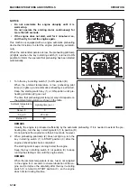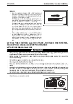
REMARK
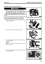
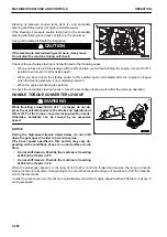
• After the engine is stopped, DEF in DEF injector and
pump is automatically purged and returned to the tank
to prevent malfunction of the devices caused by freez-
ing of DEF or deposition of urea.
For this purpose, the devices keep operating for sev-
eral minutes after starting switch (1) is turned to OFF
position, and this does not indicate abnormality.
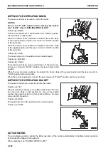
In addition, the system operating lamp lights up while
devices are operating to purge DEF to the tank. Do
not turn the battery disconnect switch to OFF position
while the system operating lamp is lit. After DEF has
been purged completely, the devices stop automatical-
ly.
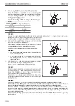
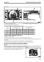
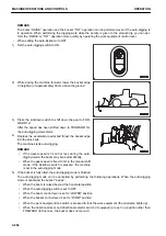
• If the starting switch (1) key is turned to OFF position
(A) while the engine is still hot, guidance (2) may be
displayed on the machine monitor. To cool down the
engine before stopping, run it at low idle the next time
and after, because it may cause damage to the devi-
ces.
METHOD FOR STARTING MACHINE (TRAVEL FORWARD AND REVERSE,
AND SHIFTING GEAR) AND STOPPING MACHINE
METHOD FOR MOVING MACHINE
k
k
WARNING
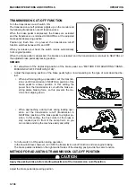
• Always disengage the frame lock bar during travelling. If it is not disengaged, the steering becomes
inoperative and this may lead to serious personal injury or death.
• Before moving the machine off, check that the area around the machine is safe, then sound the
horn before starting.
• Do not allow anyone to enter the area around the machine.
• Clear any obstacles from the travel path.
• There is a blind spot behind the machine, so be extremely careful when driving the machine in re-
verse.
• When moving the machine off at an uphill, set the transmission cut-off switch to OFF position, de-
press the accelerator pedal while depressing L.H. brake pedal and then release the brake pedal
gradually to start the machine. This prevents the machine from rolling back.
• Do not try to make directional change abruptly while the engine speed is high.
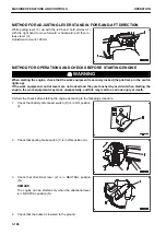
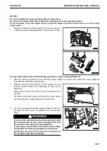
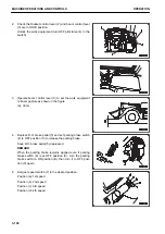
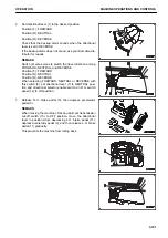
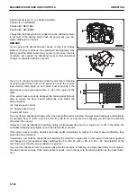
1.
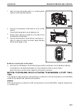
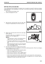
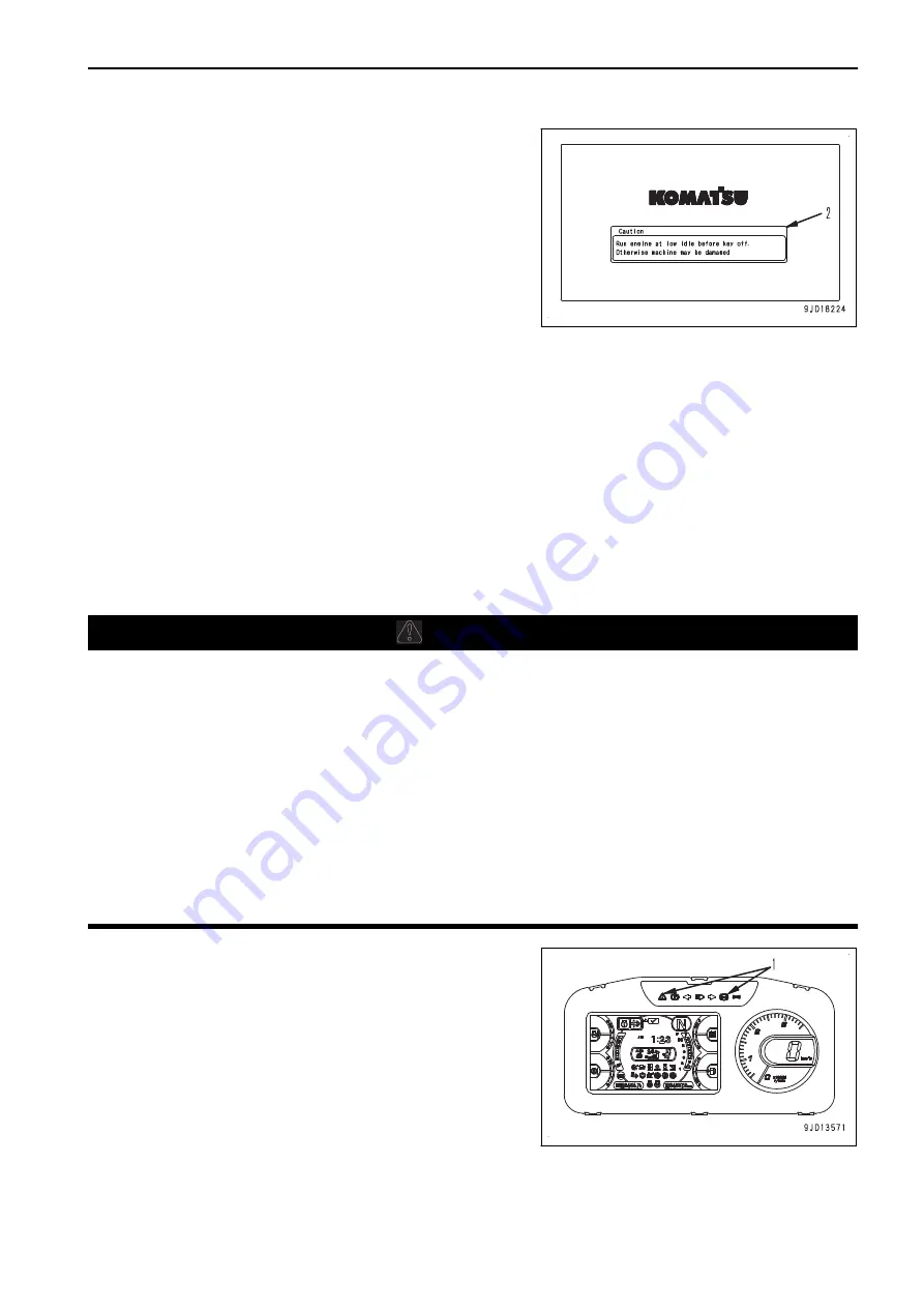
Check that caution lamp (1) is not lit.
OPERATION
MACHINE OPERATIONS AND CONTROLS
3-189
Содержание WA480-8
Страница 2: ......
Страница 19: ...Distributor name Address Phone Fax Service personnel FOREWORD PRODUCT INFORMATION 1 17...
Страница 29: ...LOCATION OF SAFETY LABELS SAFETY SAFETY LABELS 2 3...
Страница 69: ...OPERATION Please read and make sure that you understand the SAFETY section before reading this section 3 1...
Страница 76: ...Outside of cab 1 Slow blow fuse 2 Dust indicator 3 Articulation lock pin 4 Toolbox GENERAL VIEW OPERATION 3 8...
Страница 159: ...SWITCHES 1 ECSS switch 2 Front working lamp switch OPERATION EXPLANATION OF COMPONENTS 3 91...
Страница 302: ...Securing position Fixing angle A 61 B 53 C 33 D 38 TRANSPORTATION OPERATION 3 234...
Страница 324: ......
Страница 325: ...MAINTENANCE Please read and make sure that you understand the SAFETY section before reading this section 4 1...
Страница 397: ...Viewed from the rear side of the machine MAINTENANCE MAINTENANCE PROCEDURE 4 73...
Страница 402: ......
Страница 403: ...SPECIFICATIONS 5 1...
Страница 405: ...1 Value when bucket dump angle is 45 B I A G E H F D C 9 J W0 1 4 5 6 SPECIFICATIONS SPECIFICATIONS 5 3...
Страница 406: ......
Страница 422: ......
Страница 423: ...REPLACEMENT PARTS 7 1...
Страница 439: ......
Страница 440: ...WA480 8 WHEEL LOADER Form No VENAM51500 2018 KOMATSU All Rights Reserved Printed in Europe 07 2018...

