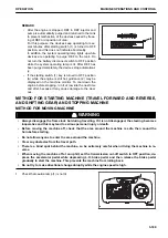
NOTICE
• Do not accelerate the engine abruptly until it is
warmed up.
Do not operate the starting motor continuously for
more than 20 seconds.
• If the engine does not start, wait for 2 minutes or so,
and then try to start the engine again.
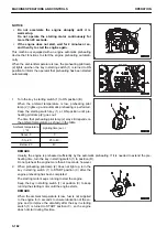
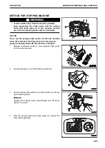
This machine is equipped with an engine automatic preheating
device that functions to start the engine preheating automati-
cally.
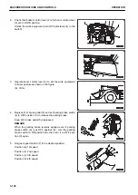
When the ambient temperature is low, the preheating pilot lamp
(2) lights up when the key in starting switch (1) is turned to ON
position to inform the operator that preheating has been started
automatically.
1.
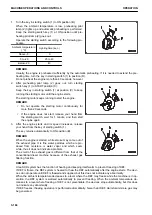
Turn the key in starting switch (1) to ON position (B).
When the ambient temperature is low, preheating pilot
lamp (2) lights up and automatic preheating is performed.
Keep the starting switch key (1) at ON position until pre-
heating pilot lamp (2) goes out.
The time that preheating pilot lamp (2) stays lit depends on
the ambient temperature as shown in the table.
Ambient temperature
( °C)
Lighting time (sec.)
Above -5
0
-5 to -20
20 to 40
Below -20
40
REMARK
Usually, the engine is preheated sufficiently by the automatic preheating. If it is needed to extend the pre-
heating time, turn the key in starting switch (1) to position (D).
Do not preheat the engine more than 40 seconds, however.
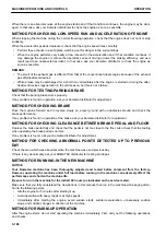
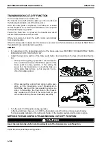
2.
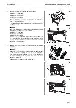
When preheating pilot lamp (2) does not light up, turn the
key in starting switch (1) to START position (C) after the
engine preheating has been completed.
The starting motor keeps running to start the engine.
Keep the key in starting switch (1) at position (C) to keep
running the starting motor until the engine starts.
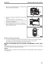
REMARK
When the ambient temperature is low, fuel is not supplied
to the engine for 3 seconds to ensure lubrication of the en-
gine and to improve the durability after the key in starting
switch (1) is turned to START position (C), so the engine
does not start during this time.
MACHINE OPERATIONS AND CONTROLS
OPERATION
3-182
Содержание WA480-8
Страница 2: ......
Страница 19: ...Distributor name Address Phone Fax Service personnel FOREWORD PRODUCT INFORMATION 1 17...
Страница 29: ...LOCATION OF SAFETY LABELS SAFETY SAFETY LABELS 2 3...
Страница 69: ...OPERATION Please read and make sure that you understand the SAFETY section before reading this section 3 1...
Страница 76: ...Outside of cab 1 Slow blow fuse 2 Dust indicator 3 Articulation lock pin 4 Toolbox GENERAL VIEW OPERATION 3 8...
Страница 159: ...SWITCHES 1 ECSS switch 2 Front working lamp switch OPERATION EXPLANATION OF COMPONENTS 3 91...
Страница 302: ...Securing position Fixing angle A 61 B 53 C 33 D 38 TRANSPORTATION OPERATION 3 234...
Страница 324: ......
Страница 325: ...MAINTENANCE Please read and make sure that you understand the SAFETY section before reading this section 4 1...
Страница 397: ...Viewed from the rear side of the machine MAINTENANCE MAINTENANCE PROCEDURE 4 73...
Страница 402: ......
Страница 403: ...SPECIFICATIONS 5 1...
Страница 405: ...1 Value when bucket dump angle is 45 B I A G E H F D C 9 J W0 1 4 5 6 SPECIFICATIONS SPECIFICATIONS 5 3...
Страница 406: ......
Страница 422: ......
Страница 423: ...REPLACEMENT PARTS 7 1...
Страница 439: ......
Страница 440: ...WA480 8 WHEEL LOADER Form No VENAM51500 2018 KOMATSU All Rights Reserved Printed in Europe 07 2018...


