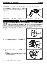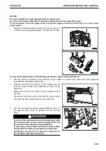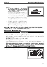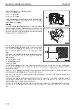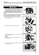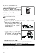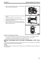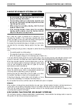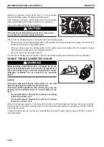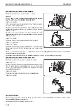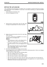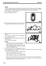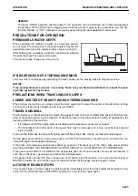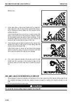
Set directional lever (1) to a desired position.
Position (F): FORWARD
Position (N): NEUTRAL
Position (R): REVERSE
Check that the backup alarm sounds when the directional lever
is set to R. If the backup alarm does not sound, ask your Ko-
matsu distributor for repairs.
REMARK
If you operate the directional lever slowly or stop it at midway
between the lever positions, the centralized warning lamp may
light up and the alarm buzzer may sound. In this case, there is
no failure, but operate the directional lever so that directional
change is completed within 2 seconds.
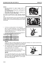
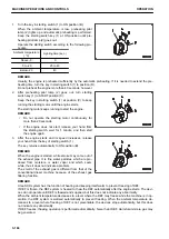
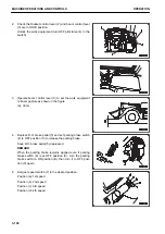
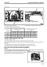
If you try to change the direction while the machine is traveling
at a high speed (when 3rd or 4th speed is used), the central-
ized warning lamp lights up and alarm buzzer sounds if the
travel speed and engine speed are in (A) or (B) region of the
table.
If the alarm buzzer sounds, depress the brake pedal immedi-
ately to reduce the travel speed sufficiently, then switch the
travel direction.
(X): Travel speed ( km/h)
(Y): Engine speed ( rpm)
In auto shift mode
If you perform a directional change when the auto shift mode is selected, the gear speed changes automatically,
for example, from F3 to R2, from F4 to R2, from R3 to F2, or from R4 to F2, allowing you to move the machine
off quicker than usual.
However, if you try directional switching during a high-speed travel such as region (A) or (B) in the table, the
centralized warning lamp lights up and the alarm buzzer sounds.
If the alarm buzzer sounds, depress the brake pedal immediately to reduce the travel speed sufficiently, then
switch the travel direction.
In particular, you must be careful about switching the direction in region (B). In this region, actual gear speed is
not changed to 2nd speed but rather switches like F3→R3, F4→R4 or R3→F3, R4→ F4. Deceleration of the
machine is less than the one available in region (A).
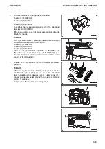
If you set the directional lever to position (N) while the machine is traveling at a high speed (25 km/h or higher),
the alarm buzzer sounds. If the alarm buzzer sounds, return the lever to the same position as the travel direc-
tion.
MACHINE OPERATIONS AND CONTROLS
OPERATION
3-194
Содержание WA480-8
Страница 2: ......
Страница 19: ...Distributor name Address Phone Fax Service personnel FOREWORD PRODUCT INFORMATION 1 17...
Страница 29: ...LOCATION OF SAFETY LABELS SAFETY SAFETY LABELS 2 3...
Страница 69: ...OPERATION Please read and make sure that you understand the SAFETY section before reading this section 3 1...
Страница 76: ...Outside of cab 1 Slow blow fuse 2 Dust indicator 3 Articulation lock pin 4 Toolbox GENERAL VIEW OPERATION 3 8...
Страница 159: ...SWITCHES 1 ECSS switch 2 Front working lamp switch OPERATION EXPLANATION OF COMPONENTS 3 91...
Страница 302: ...Securing position Fixing angle A 61 B 53 C 33 D 38 TRANSPORTATION OPERATION 3 234...
Страница 324: ......
Страница 325: ...MAINTENANCE Please read and make sure that you understand the SAFETY section before reading this section 4 1...
Страница 397: ...Viewed from the rear side of the machine MAINTENANCE MAINTENANCE PROCEDURE 4 73...
Страница 402: ......
Страница 403: ...SPECIFICATIONS 5 1...
Страница 405: ...1 Value when bucket dump angle is 45 B I A G E H F D C 9 J W0 1 4 5 6 SPECIFICATIONS SPECIFICATIONS 5 3...
Страница 406: ......
Страница 422: ......
Страница 423: ...REPLACEMENT PARTS 7 1...
Страница 439: ......
Страница 440: ...WA480 8 WHEEL LOADER Form No VENAM51500 2018 KOMATSU All Rights Reserved Printed in Europe 07 2018...

