


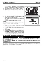


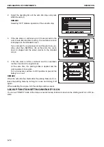


If the condition for reversing the fan is not satisfied,
changeover condition waiting pilot lamp (4) lights up in red.
5.
Set the engine speed to high idle and perform cleaning.
6.
After finishing cleaning, set the engine speed to low idle.
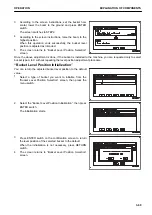
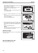
7.
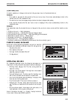
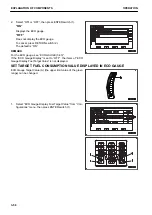
If the menu switch is pressed on the standard screen, the
screen shown in the figure is displayed.
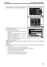
Press ENTER switch to return the fan to the normal rota-
tion mode.
Fan reverse pilot lamp (3) flashes, then goes out.
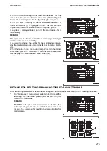
REMARK
If one of the following conditions is satisfied, the fan rotation re-
turns from reverse direction to normal direction.
• Perform the manual fan reverse operation again while the
fan is rotating in reverse.
• 10 minutes elapses after the fan rotation direction is re-
versed.
• Stop the engine.
• The coolant temperature, hydraulic oil temperature, or tor-
que converter oil temperature overheats (the caution lamp
of the oil temperature gauge or coolant temperature gauge
on the machine monitor lights up in red, then action level
“L02” is displayed) while the fan is rotating in reverse.
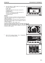
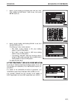
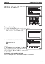
RADIATOR FAN AUTOMATIC REVERSE MODE
k
k
CAUTION
When rotating the fan in the reverse direction, beware extremely that dirt will not fly out and cloth, etc.
will not be wound in the fan.
Dust may be blown up. Check that there is no people in the surrounding area while the fan is rotating in
the reverse direction.
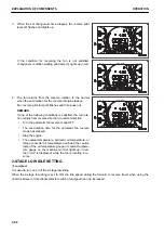
In the automatic fan reverse mode, you can configure the setting for automatically rotating the fan in the reverse
direction to blow off mud and dirt sticking to the radiator.
EXPLANATION OF COMPONENTS
OPERATION
3-64
Содержание WA480-8
Страница 2: ......
Страница 19: ...Distributor name Address Phone Fax Service personnel FOREWORD PRODUCT INFORMATION 1 17...
Страница 29: ...LOCATION OF SAFETY LABELS SAFETY SAFETY LABELS 2 3...
Страница 69: ...OPERATION Please read and make sure that you understand the SAFETY section before reading this section 3 1...
Страница 76: ...Outside of cab 1 Slow blow fuse 2 Dust indicator 3 Articulation lock pin 4 Toolbox GENERAL VIEW OPERATION 3 8...
Страница 159: ...SWITCHES 1 ECSS switch 2 Front working lamp switch OPERATION EXPLANATION OF COMPONENTS 3 91...
Страница 302: ...Securing position Fixing angle A 61 B 53 C 33 D 38 TRANSPORTATION OPERATION 3 234...
Страница 324: ......
Страница 325: ...MAINTENANCE Please read and make sure that you understand the SAFETY section before reading this section 4 1...
Страница 397: ...Viewed from the rear side of the machine MAINTENANCE MAINTENANCE PROCEDURE 4 73...
Страница 402: ......
Страница 403: ...SPECIFICATIONS 5 1...
Страница 405: ...1 Value when bucket dump angle is 45 B I A G E H F D C 9 J W0 1 4 5 6 SPECIFICATIONS SPECIFICATIONS 5 3...
Страница 406: ......
Страница 422: ......
Страница 423: ...REPLACEMENT PARTS 7 1...
Страница 439: ......
Страница 440: ...WA480 8 WHEEL LOADER Form No VENAM51500 2018 KOMATSU All Rights Reserved Printed in Europe 07 2018...


